CG Drives & Automation, 01-5980-01r2 Functionality 127
Flip-flop 1 Reset Delay [6415]
The RESET input signal for Flip-flop 1 is delayed with the
set value in this menu.
Flip-flop 1 Timer Value [6416]
This menu shows the actual value of the flip-flop 1 timer.
Flip-flop 2 - 4 [642] - [644]
Refer to the descriptions for flip-flop 1. Default for
[6421]”F2 Mode” is “Reset”. For [6431]”F3 Mode” the
default is “Set”, and for [6441] “F4 Mode” the default is
“Edge”.
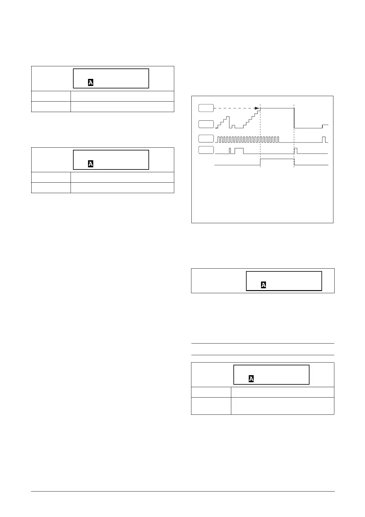
8.6.5 Counters [650]
The counter function counts pulses and can signal on a
selected output when the counter reaches a specified level.
The counter counts up on the positive edges of the trigger
signal, and it is zeroed when the reset signal is active.
When the counter value equals the trip value, the counter
output signal (CTR1 or CTR2) is activated. See Fig. 74.
Fig. 74 Counters, principle.
Counter 1 [651]
Counter 1 parameter group.
Counter 1 Trigger [6511]
The selected signal is used as a trigger signal for counter 1.
Counter 1 is incremented by 1 on every positive edge of the
trigger signal.
Default: 0:00:00.0 (hours:minutes:seconds)
Range: 0:00:00.0–9:59:59.9
Read-only
Default: 0:00:00.0 (hours:minutes:seconds)
Range: 0:00:00.0–9:59:59.9
6415 F1 Res Dly
Stp 0:00:00.0
6416 F1 Tmr Val
Stp 0:00:00.0
NOTE: Maximum counting frequency is 8 Hz.
Default: Off
Selection:
Same selections as in menu Relay 1 [551],
page 112.
CTR1
6513
6519
6511
6512
CTR1= Counter 1 output signal
6511= Counter 1 Trigger
6512= Counter 1 Reset
6513= Counter 1 Trip Value
6519= Counter 1 Value

 Loading...