CG Drives & Automation, 01-5980-01r2 Functionality 121
8.6.2 Logic outputs [620]
Logic 1 [621]
By means of an expression editor, the input signals can be
logically combined into the logics function to create a logic
output signal.
The expression editor has the following features:
• The following input signals can be used:
CA1-CA4, CD1-CD4, L1-L4, T1Q-T4Q, F1-F4, and
CTR1-CTR2.
• The following inverted input signals can be used:
!A1-!A4, !D1-!D4, !L1- !L4, !T1Q-!T4Q, !F1-!F4, and
!CTR1-!CTR2.
• The following logical operators are available:
"+" : OR operator
"&" : AND operator
"^" : EXOR operator
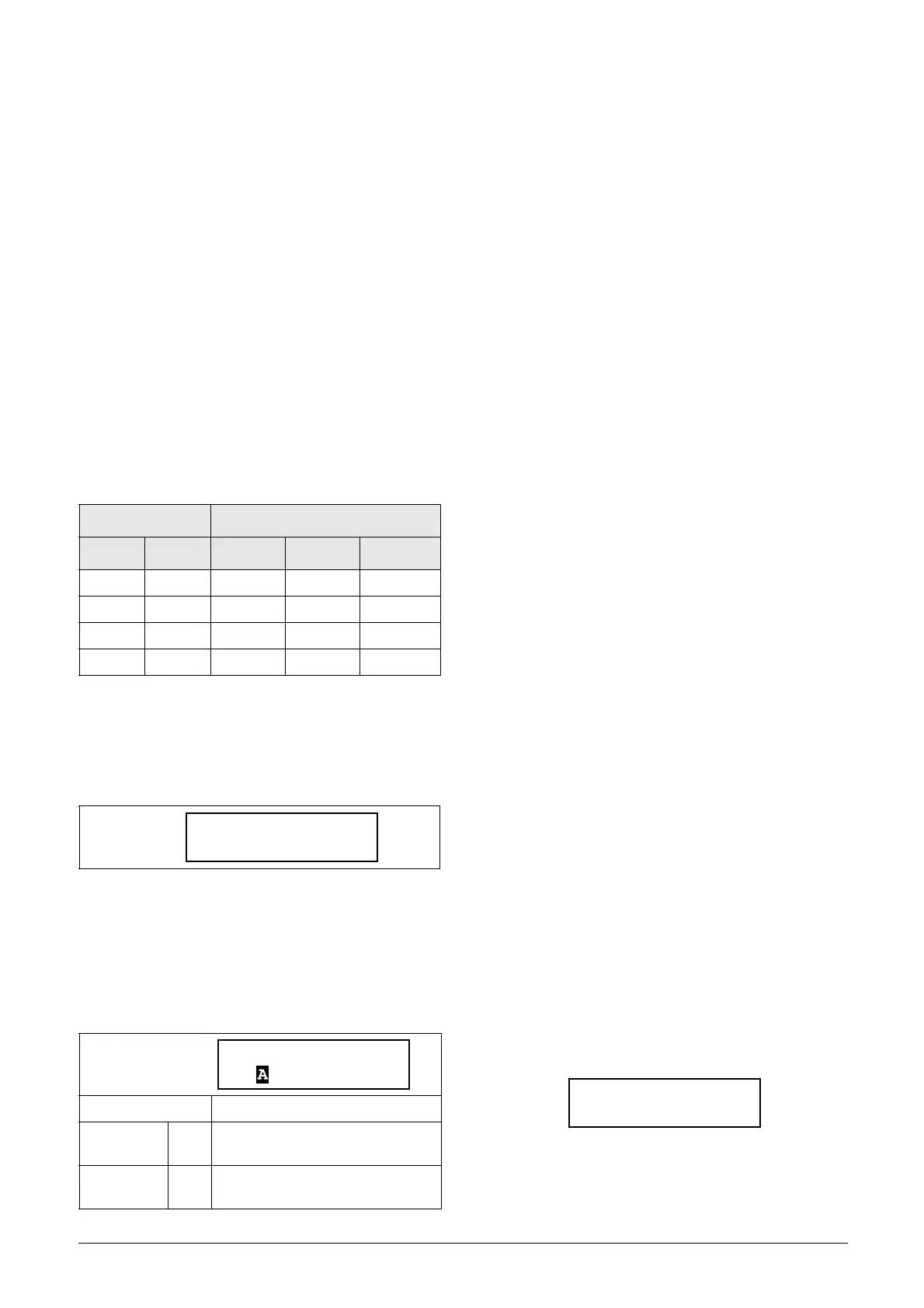
Expressions according to the following truth table can be
made (see also the example below):
The output signal can be programmed to the relay outputs or
used as a virtual connection source [560].
The logic expression must be programmed by means of the
menus [6211] to [621B], and its actual appearance can be
viewed in menu [621], with example below:
Menu [621]shows the actual values of the four selected input
signals set in menus [6212], [6214], [6216] and [6218].
Logic 1 Expression [6211]
Selection of execution order of the logic expression for the
Logic 1 function:
• Parentheses ( ) show the order in which the Logic 1
Inputs are combined, according to [6211].
• 1, 2, 3, and 4, represent the Logic 1 Input signals
selected in menu [6212], [6214], [6216], and [6218].
• The dots stand for the Logic 1 Operators (&, +, or ^),
whose values are selected in menus [6213], [6215], and
[6217].
To build the Logic 1 expression using the default selection in
menu [6211], the execution order is as follows:
1. Input 1 is combined with Input 2 using Operator 1.
2. Input 3 is combined with the expression (1.2), using
Operator 2.
3. Input 4 is combined with the result of (1.2).3, using
Operator 3.
The alternative execution order leads to:
1. Input 1 is combined with Input 2 using Operator 1.
2. Input 3 is combined with Input 4 using Operator 3.
3. Expression (1.2) is combined with expression (3.4),
using Operator 2.
Example:
Input 1 = CA1, set in menu [6212]
Input 2 = F1, menu [6214]
Input 3 = T1Q, menu [6216]
Input 4 = !A2, menu [6218]
Operator 1 = & (AND), set in menu [6213]
Operator 2 = + (OR), menu [6215]
Operator 3 = & (AND), menu [6217]
The following expression is created, using the menus above:
CA1&F1+T1Q&!A2
With the default setting for L1 Expression this is
representing:
((CA1&F1)+T1Q)&!A2
Let’s use the following values on the input signals as an
example:
CA1=1 (active/high)
F1= 1 (active/high)
T1Q = 1 (active/high)
!A2 = 0 (inactive/low)
With the respective values inserted the resulting logic
expression is:
which is equal to 0.
With the alternative execution order for the L1 Expression
this is representing:
Input Result
A B & (AND) + (OR) ^(EXOR)
00 0 0 0
01 0 1 1
10 0 1 1
11 1 1 0
Read-only
Default: ((1.2).3).4
((1.2).3).4 0
Default execution order, see
explanation below.
(1.2).(3.4) 1
Alternative execution order, see
explanation below.
621 Logic 1
Stp ((0&1)&0)&0
6211 L1 Expr
Stp ((1.2).3).4
621 Logic 1
Stp ((1&1)+1)&0
 Loading...
