CG Drives & Automation 01-5980-01r2 Technical data 163
13.4 Control power- and I/O signal connectors
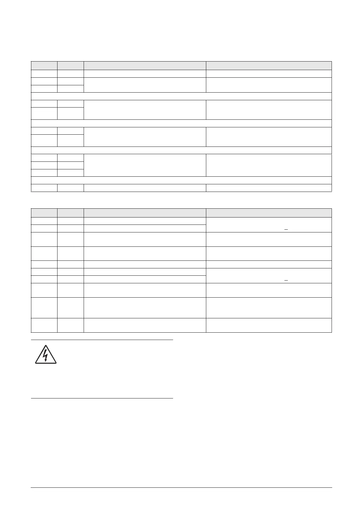
Table 49 Power board connections.
Terminal Function Electrical characteristics
PE Protective Earth Protective grounding
N
Control supply voltage 100-240 VAC ±10%
L
21 NO Programmable relay 1. Factory setting is
“Operation” with indication by closing contact on
terminals 21 to 22.
1-pole closing contact (NO), 250 VAC 8 A or 24 VDC
8 A resistive, 250 VAC, 3 A inductive. Min. 100 mA.
See Warning.
22 C
23 NO
Programmable relay 2. Factory setting is “Off” with
indication by closing contact on terminals 23 to 24.
1-pole closing contact (NO), 250 VAC 8 A or 24 VDC
8 A resistive, 250 VAC, 3 A inductive. Min. 100 mA.
See Warning.
24 C
31 NO
Programmable relay 3. Factory setting is “Trip”.
Indication by closing contact on terminals 31 to 32
and opening contact on 32 to 33.
1-pole change-over contact (NO/NC), 250 VAC 8A or
24 VDC 8A resistive, 250 VAC, 3A inductive.
Min. 100 mA. See Warning.
32 C
33 NC
69-70 PTC Thermistor input Alarm level 2.4 kΩ. Switch back level 2.2 kΩ.
Table 50 Control board connections.
Terminal Function Electrical characteristics
11 Digital input 1. Factory setting is “Run FWD”
0-4 V --> 0; 8-27 V--> 1. Max. 37 V for 10 sec.
Impedance: <3.3 VDC: 4.7 kΩ. - >
3.3 VDC: 3.6 kΩ
12 Digital input 2. Factory setting is “Stop”.
13 Control signal supply voltage to analogue input.
+10 VDC ±5%. Max. current from +10 VDC: 10 mA.
Short circuit-proof and overload-proof.
14
Analogue input, 0-10 V, 2-10 V, 0-20 mA and
4-20 mA/digital input. S1 jumper for U/I selection.
Impedance to terminal 15 (0 VDC) voltage signal:
20 kΩ, current signal: 250 Ω.
15 GND (common) 0 VDC signal ground
16 Digital input 3. Factory setting is “Set Ctrl 1”
0-4 V --> 0; 8-27 V--> 1. Max. 37 V for 10 sec.
Impedance: <3.3 VDC: 4.7 kΩ. - >
3.3 VDC: 3.6 kΩ
17 Digital input 4. Factory setting is “Reset”
18 Control signal supply 1, voltage to digital input.
+24 VDC ±5%. Max. current from +24 VDC = 50 mA.
Short circuit-proof and overload-proof.
19 Analogue output. Factory setting is “Current”.
Analogue output contact:
0-10 V, 2-10 V; min load impedance 700 Ω
0-20 mA and 4-20 mA; max load impedance 700 Ω
20 Control signal supply 2, voltage to digital input.
+24 VDC ±5%. Max. current from +24 VDC = 50 mA.
Short circuit-proof and overload-proof.
WARNING!
The same external supply voltage level (max
24 VDC or max 250 VAC) must be used for all
three output relays (terminals 21-33).
Do not mix AC and DC voltage.
Make sure to use the same voltage level
within this terminal section, otherwise the
softstarter may be damaged.
 Loading...
