112 Functionality CG Drives & Automation, 01-5980-01r2
8.5.4 Relays [550]
Submenu with all the settings for the relay outputs. The relay
mode selection makes it possible to establish a “fail safe” relay
operation by using the normal closed contact to function as
the normal open contact.
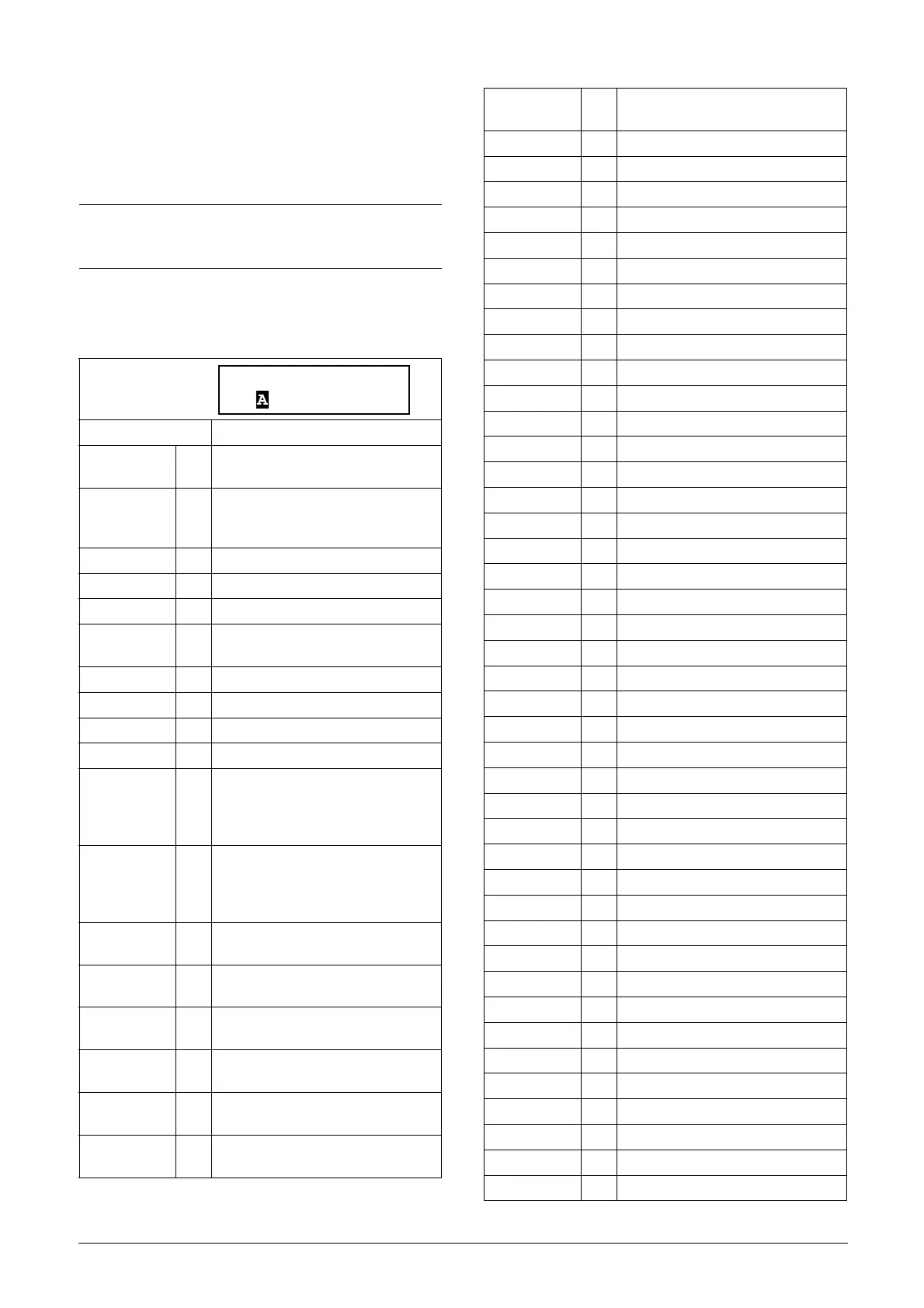
Relay 1 [551]
Sets the function for the relay output 1.
NOTE: Additional relays will become available when I/O
option boards are connected. Maximum 2 boards with 3
relays each.
Default: Operation
Off 0
Output is not active and constantly
low.
On 1
Output is made constantly high, i.e.
for checking circuits and trouble
shooting.
Operation 2 Motor is active, See Fig. 63
No Operation 3 Inverted operation
Bypass mode 4 Bypass activated. See Fig. 63
Acc/Dec 5
The speed is increasing or decreasing
along the acc. ramp/dec. ramp.
No Trip 6 No Trip condition active.
Trip 7 A Trip condition is active.
AutoRst Trip 8 Autoreset trip condition active.
Warning 9 A Warning condition is active.
Ready 10
The softstarter is ready for operation
and to accept a start command. This
means that the softstarter is powered
up and ready to start.
I>I
n_mot
11
The output current is higher than the
motor nominal current [224], reduced
according to Motor ventilation [228].
See Chapter 8.2.4 page 76.
RevCurrBrake 12
The output is used to control a
contactor for reverse current brake.
LoadMonAlarm 13
Max or min alarm condition active
(trip or warning).
Pre Alarm 14
Max or min pre-alarm condition active
(trip or warning).
Max Alarm 15
Max alarm condition active (trip or
warning).
Max PreAlarm 16
Max pre-alarm condition active (trip or
warning).
Min Alarm 17
Min alarm condition active (trip or
warning).
Min PreAlarm 18
Min pre-alarm condition active (trip or
warning).
CA 1 19 Analogue comparator 1 output.
!A1 20 Analogue comp 1 inverted output.
CA 2 21 Analogue comparator 2 output.
!A2 22 Analogue comp 2 inverted output.
CA 3 23 Analogue comparator 3 output.
!A3 24 Analogue comp 3 inverted output.
CA 4 25 Analogue comparator 4 output.
!A4 26 Analogue comp 4 inverted output.
CD 1 27 Digital comparator 1 output.
!D1 28 Digital comp 1 inverted output.
CD 2 29 Digital comparator 2 output.
!D2 30 Digital comp 2 inverted output.
CD 3 31 Digital comparator 3 output.
!D3 32 Digital comp 3 inverted output.
CD 4 33 Digital comparator 4 output.
!D4 34 Digital comp 4 inverted output.
T1Q 35 Logic timer 1 output
!T1Q 36 Inverted logic timer 1 output
T2Q 37 Logic timer 2 output
!T2Q 38 Inverted logic timer 2 output
T3Q 39 Logic timer 3 output
!T3Q 40 Inverted logic timer 3 output
T4Q 41 Logic timer 4 output
!T4Q 42 Inverted logic timer 4 output
L1 43 Logic output 1.
!L1 44 Logic output 1 inverted.
L2 45 Logic output 2.
!L2 46 Logic output 2 inverted.
L3 47 Logic output 3.
!L3 48 Logic output 3 inverted.
L4 49 Logic output 4.
!L4 50 Logic output 4 inverted.
F1 51 Flip-flop output 1.
!F1 52 Flip-flop output 1 inverted.
F2 53 Flip-flop output 2.
!F2 54 Flip-flop output 2 inverted.
F3 55 Flip-flop output 3.
!F3 56 Flip-flop output 3 inverted.
F4 57 Flip-flop output 4.
!F4 58 Flip-flop output 4 inverted.
CTR1 59 Counter output 1.
!CTR1 60 Counter output 1 inverted.
 Loading...
