CG Drives & Automation, 01-5980-01r2 Functionality 125
Timer 1 Delay [6313]
This menu is only visible when “Timer Mode “[6312] is set
to “Delay”. When Timer 1 is triggered in menu [6311], the
set value in this menu will delay the activation of the Timer
1 output signal, T1Q.
Timer 1 T1 [6314]
This menu sets the “on” time for the “Alternate” and “On-
time” modes in menu [6312] (only visible when one of these
two modes has been selected).
If “Alternate” mode is selected and Timer 1 is triggered on
signal set up in [6311], the timer will automatically keep
switching from the “on” time ([6314] “Timer 1 T1”) to the
“off” time ([6315]”Timer 1 T2”). Hence the output signal
T1Q will alternate between active, “on”, and inactive, “off ”.
See Fig. 71.
If “On-time” mode is selected in [6312] and Timer 1 is
triggered in [6311], the timer will extend the activation (“on”
time) of the output signal T1Q to the set value in
[6314]“Timer 1 T1”. See Fig. 72.
Timer 1 T2 [6315]
In this menu the “off” time in the “Alternate” mode is set.
Timer 1 Value [6316]
This menu shows the actual value of the timer.
Timer 2 - 4 [632] - [634]
Refer to the descriptions for Timer 1.
8.6.4 SR Flip-flops [640]
The flip-flop function is a memory circuit that can be used to
store data concerning state. The output from a flip-flop is
dependent not only on its current input, but also on its state
at the moment this is received (hence previous input status
also matters).
The set/reset flip-flop circuit has two input signals, SET and
RESET, that control the state of an output signal, OUT.
When none of the input signals are active (i.e. both are =0),
the flip-flop will keep its current value.
When only one of the input signals is active (=1), this will
directly decide the status of the output signal. Consequently
if SET=1 (active) and RESET=0 (inactive), the SET
command is given to the output signal, OUT. This will result
in a signal change from inactive to active (=1), if not already
in an active state.
Conversely, if SET=0 (inactive) and RESET=1 (active), the
RESET command is given to the output signal, OUT,
causing this to be deactivated (=0).
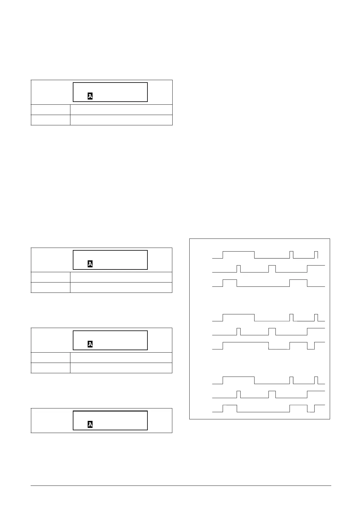
Flip-flop priority mode
When both input signals are in an active state simultaneously,
i.e. SET=1 and RESET=1, a priority function decides which
signal will influence the output signal. There are three
different priority settings available for the flip-flop function,
selected in the menu for “Flip-flop Mode”. Examples of the
different priority settings are presented in Fig. 73.
Fig. 73 Programmable flip-flop modes.
Default: 0:00:00.0 (hours:minutes:seconds)
Range: 0:00:00.0–9:59:59.9
Default: 0:00:00.0 (hours:minutes:seconds)
Range: 0:00:00.0–9:59:59.9
Default: 0:00:00.0 (hours:minutes:seconds)
Range: 0:00:00.0–9:59:59.9
Read-only
6313 Timer1 Dly
Stp 0:00:00.0
6314 Timer1 T1
Stp 0:00:00.0
6315 Timer1 T2
Stp 0:00:00.0
6316 Timer1 Val
Stp 0:00:00.0
RESET
SET
OUT
RESET
SET
OUT
RESET
SET
OUT
Reset priority
Set priority
Edge controlled without priority
 Loading...
