3-15
Catalyst 6500 Series Switches Installation Guide
OL-5781-04
Chapter 3 Installing the Switch
Installing the Switch Chassis in the Rack
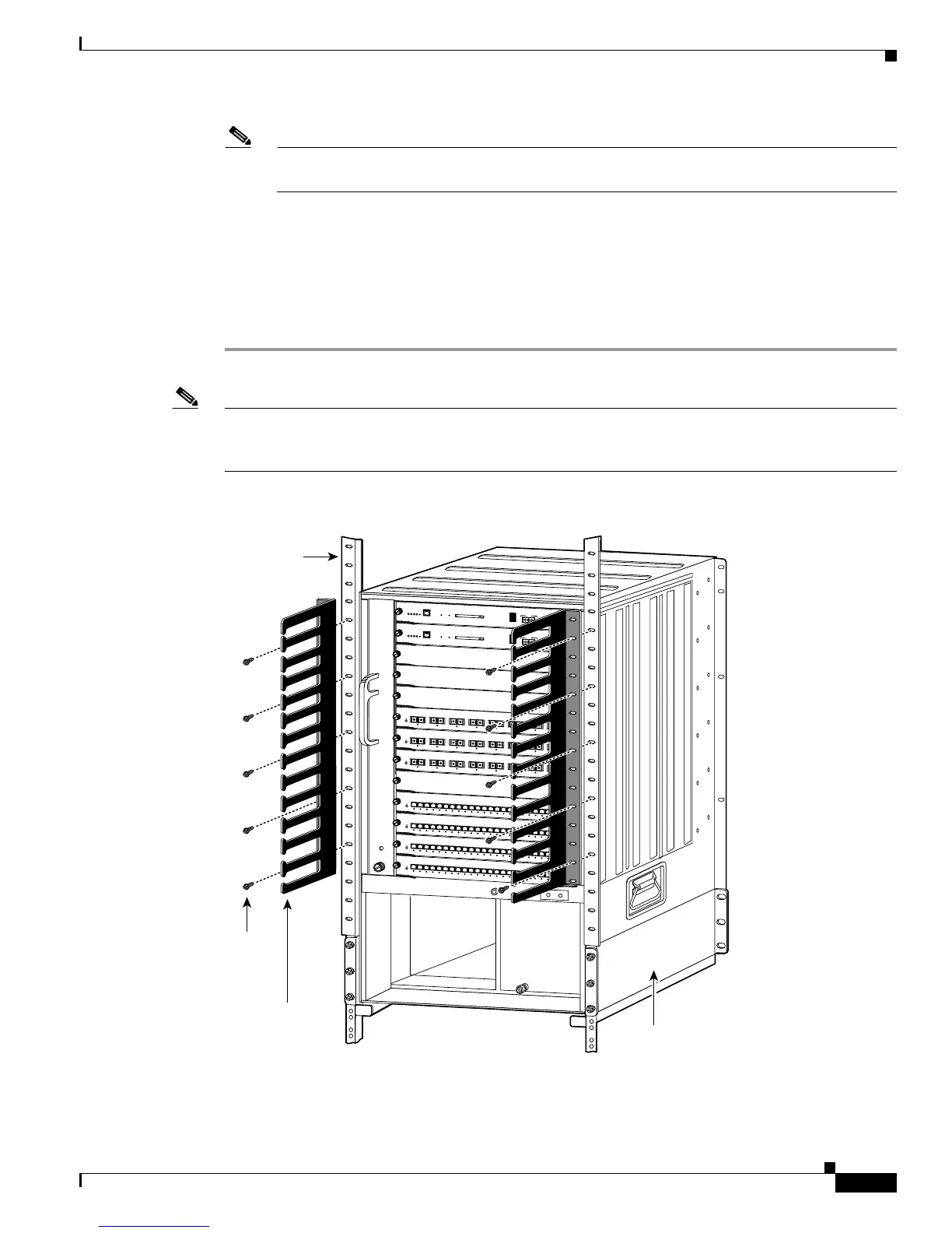
Note If you are rack-mounting the Catalyst 6513 switch and you want to install the optional cable
guides, perform Step 5; if not, go to Step 6.
Step 4 Align the cable guide bracket mounting holes with the mounting holes in the L bracket and the mounting
holes in the equipment rack, and install ten (five per side) 12-24 x 3/4-inch or 10-32 x 3/4-inch screws,
as shown in Figure 3-9.
Step 5 Install the eight or ten (four or five per side) 12-24 x 3/4-inch or 10-32 x 3/4-inch screws through the
holes in the L bracket and into the threaded holes in the equipment rack posts.
Step 6 Use a tape measure and level to verify that the chassis is installed straight and level.
Note If you are not rack-mounting the Catalyst 6513 switch and you are installing the optional cable guide
assemblies, you must obtain ten 12x24 or 10x32 nuts. Use the screws supplied in the accessory kit and
the nuts you obtained to attach the cable guide assembly to the L bracket.
Figure 3-9 Installing the Catalyst 6513 Switch in the Rack with the Optional Cable Guides
FAN
STATUS
8 PORT GIGABIT ETHERNET
WS-X6408
1
LIN
K
STATUS
2
34
5
6
7
8
L
IN
K
LINK
LIN
K
L
IN
K
LIN
K
L
IN
K
LIN
K
8 PORT GIGABIT ETHERNET
WS-X6408
1
LINK
STATUS
2
3
4
56
7
8
LIN
K
LIN
K
LIN
K
LIN
K
LIN
K
L
IN
K
LINK
8 PORT GIGABIT ETHERNET
WS-X6408
1
LIN
K
STATUS
2
34
5
6
7
8
L
IN
K
L
IN
K
LIN
K
LIN
K
LIN
K
L
IN
K
LINK
2
4
P
O
R
T
1
0
0
F
X
W
S
-
X
6
2
2
4
S
T
A
T
U
S
2
4
P
O
R
T
1
0
0
F
X
W
S
-
X
6
2
2
4
S
T
A
T
U
S
2
4
P
O
R
T
1
0
0
F
X
W
S
-
X
6
2
2
4
S
T
A
T
U
S
2
4
P
O
R
T
1
0
0
F
X
W
S
-
X
6
2
2
4
S
T
A
T
U
S
1
LINK
2
LINK
3
LINK
4
LINK
5
LINK
6
LINK
7
LINK
8
LINK
9
LINK
1
0
LINK
1
1
LINK
1
2
LINK
1
3
LINK
1
4
LINK
1
5
LINK
1
6
LINK
1
7
LINK
1
8
LINK
1
9
LINK
2
0
LINK
2
1
LINK
2
2
LINK
2
3
LINK
2
4
LINK
1
L
I
N
K
2
L
I
N
K
3
L
I
N
K
4
L
I
N
K
5
L
I
N
K
6
L
I
N
K
7
L
I
N
K
8
L
I
N
K
9
L
I
N
K
1
0
L
I
N
K
1
1
L
I
N
K
1
2
L
I
N
K
1
3
L
I
N
K
1
4
L
I
N
K
1
5
L
I
N
K
1
6
L
I
N
K
1
7
L
I
N
K
1
8
L
I
N
K
1
9
L
I
N
K
2
0
L
I
N
K
2
1
L
I
N
K
2
2
L
I
N
K
2
3
L
I
N
K
2
4
L
I
N
K
1
L
I
N
K
2
L
I
N
K
3
L
I
N
K
4
L
I
N
K
5
L
I
N
K
6
L
I
N
K
7
L
I
N
K
8
L
I
N
K
9
L
I
N
K
10
L
I
N
K
11
L
I
N
K
12
L
I
N
K
13
L
I
N
K
14
L
I
N
K
15
L
I
N
K
16
L
I
N
K
17
L
I
N
K
18
L
I
N
K
19
L
I
N
K
20
L
I
N
K
21
L
I
N
K
22
L
I
N
K
23
L
I
N
K
24
L
I
N
K
1
L
I
N
K
2
L
I
N
K
3
L
I
N
K
4
L
IN
K
5
L
I
N
K
6
L
I
N
K
7
L
I
N
K
8
L
I
N
K
9
L
I
N
K
1
0
L
I
N
K
1
1
L
I
N
K
1
2
L
I
N
K
1
3
L
I
N
K
1
4
L
I
N
K
1
5
L
I
N
K
1
6
L
I
N
K
1
7
L
I
N
K
1
8
L
I
N
K
1
9
L
IN
K
2
0
L
I
N
K
2
1
L
IN
K
2
2
L
IN
K
2
3
L
I
N
K
2
4
L
I
N
K
SUPERVISOR2
WS-X6K-SUP2-2GE
S
T
A
T
U
S
S
Y
S
T
E
M
C
O
N
S
O
L
E
P
W
R
M
G
M
T
R
E
S
E
T
CONSOLE
CONSOLE
PORT
MODE
PCMCIA
EJECT
PORT 1
PORT 2
Switch Load
100%
1%
LIN
K
LIN
K
SUPERVISOR2
WS-X6K-SUP2-2GE
S
T
A
T
U
S
S
Y
S
T
E
M
C
O
N
S
O
L
E
P
W
R
M
G
M
T
R
E
S
E
T
CONSOLE
CONSOLE
PORT
MODE
PCMCIA
EJECT
PORT 1
PORT 2
Switch Load
100%
1%
LINK
LINK
1
2
3
4
5
6
7
8
9
10
11
12
13
48125
12 x 24
or
10 x 32
(10x)
Shelf
bracket
Cable guide
L-bracket