3-21
Catalyst 6500 Series Switches Installation Guide
OL-5781-04
Chapter 3 Installing the Switch
Installing the Cable Management System (Catalyst 6509-NEB-A Switch Only)
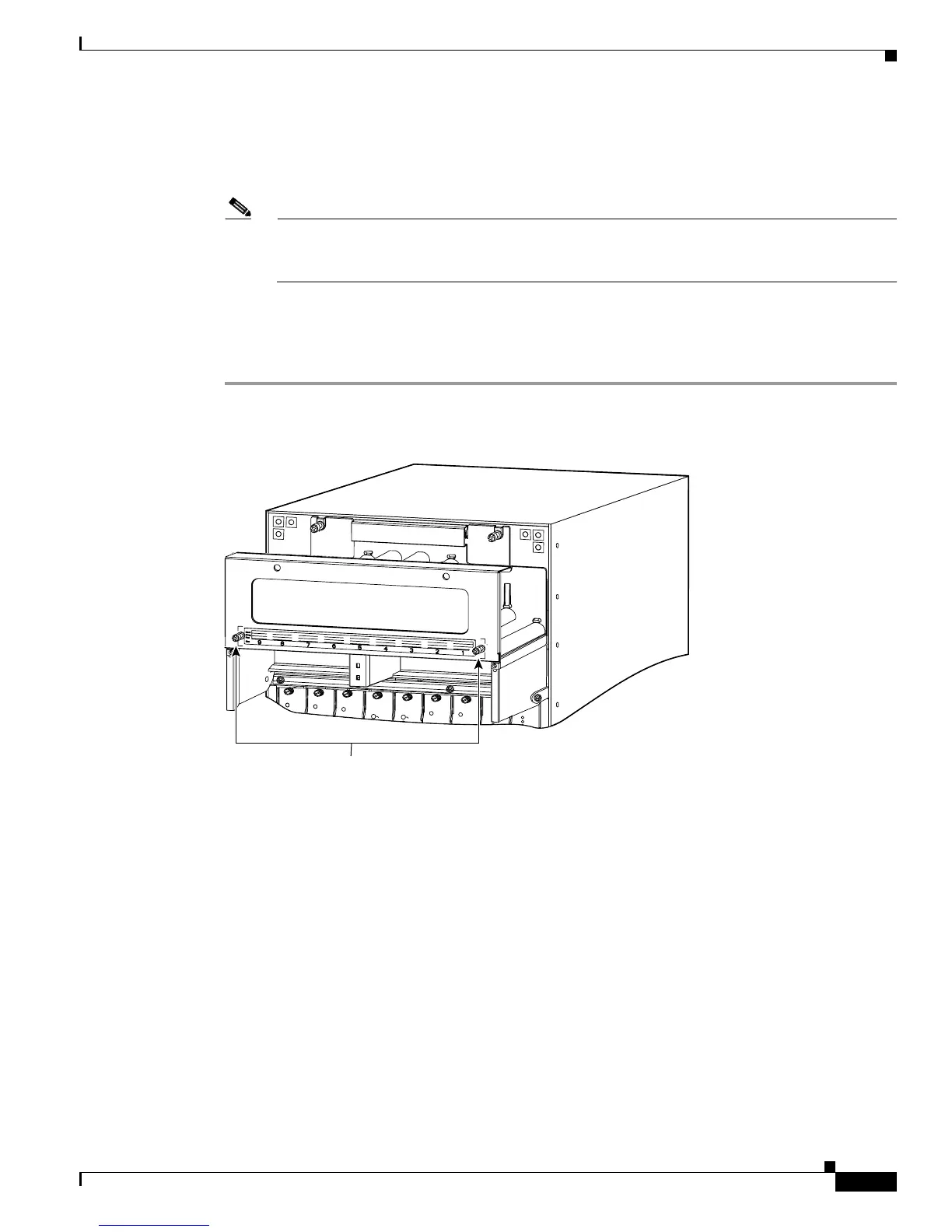
Step 4 Install the standard cable guide to the back panel by hooking the lip of the cable guide to the back panel.
(See Figure 3-14.)
Step 5 Install the two screws to secure the cable guide to the back plate. (See Figure 3-14.)
Note Before installing the front panel, attach the interface cables to the modules, and route the cables
through the cable guide. See the “Attaching the Interface Cables” section on page 3-28 for
information on attaching the interface cables.
Step 6 Attach the interface cables to the modules, and route the cables through the cable guide.
Step 7 Install the front panel by hooking the top of the front panel over the cable guide.
Step 8 Tighten the two captive installation screws. (See Figure 3-15.)
Figure 3-15 Front Panel Installation
S
U
P
E
R
V
IS
O
R
2
W
S
-X
6
K
-S
U
P
2
-
2
G
E
S
T
A
T
U
S
S
Y
S
T
E
M
S
U
P
E
R
V
I
S
O
R
2
W
S
-
X
6
K
-S
U
P
2
-2
G
E
S
T
A
T
U
S
S
Y
S
T
E
M
S
W
I
T
C
H
F
A
B
R
I
C
M
D
L
STATUS
W
S
-
C
6
5
0
0
-
S
F
M
S
W
IT
C
H
F
A
B
R
I
C
M
D
L
STAT
W
S
-
C
6
5
0
0
-
S
F
M
O
C
1
2
P
O
S
M
M
O
S
M
-
4
0
C
1
2
-
P
O
S
-
M
M
S
T
A
T
U
S
O
C
1
2
P
O
S
M
M
O
S
M
-
4
0
C
1
2
-
P
O
S
-
M
M
S
T
A
T
U
S
O
C
1
2
P
O
S
M
M
O
S
M
-
4
0
C
1
2
-
P
O
S
-M
M
S
T
A
T
U
S
8 PORT OC3 POS MM
OSM-8OC3-POS MM
S
T
A
T
U
S
8 PORT OC3 POS
OSM-8OC3-POS MM
S
T
A
T
U
S
99970
FAN
STATUS
FAN
1
FAN
2
Captive installation screws