3-34
Catalyst 6500 Series Switches Installation Guide
OL-5781-04
Chapter 3 Installing the Switch
Attaching the Interface Cables
Step 9 Remove the dust plugs from the SFP transceiver optical bores.
Step 10 Immediately attach the network interface cable LC connector to the SFP transceiver.
Step 11 To connect 1000BASE-T SFP transceivers to a copper network, perform the following substeps:
Caution To comply with GR-1089 intrabuilding lightning immunity requirements, you must use grounded,
shielded, twisted-pair, Category 5 cabling.
a. Insert the Category 5 network cable RJ-45 connector into the SFP transceiver socket.
Note When connecting to a 1000BASE-T-compatible server, workstation, or router, use four
twisted-pair, straight-through Category 5 cabling for the SFP transceiver port. When
connecting to a 1000BASE-T-compatible switch or repeater, use four twisted-pair, crossover
Category 5 cabling.
b. Insert the other end of the network cable into an RJ-45 port on a 1000BASE-T-compatible target
device.
Step 12 Observe the port status LED:
• The LED turns green when the SFP transceiver and the target device have an established link.
• The LED turns amber while STP discovers the network topology and searches for loops. This
process takes about 30 seconds, and then the LED turns green.
• If the LED is off, the target device might not be turned on, there might be a cable problem, or
there might be a problem with the adapter that is installed in the target device. Refer to the
Troubleshooting section of your switch hardware guide for solutions to cabling problems.
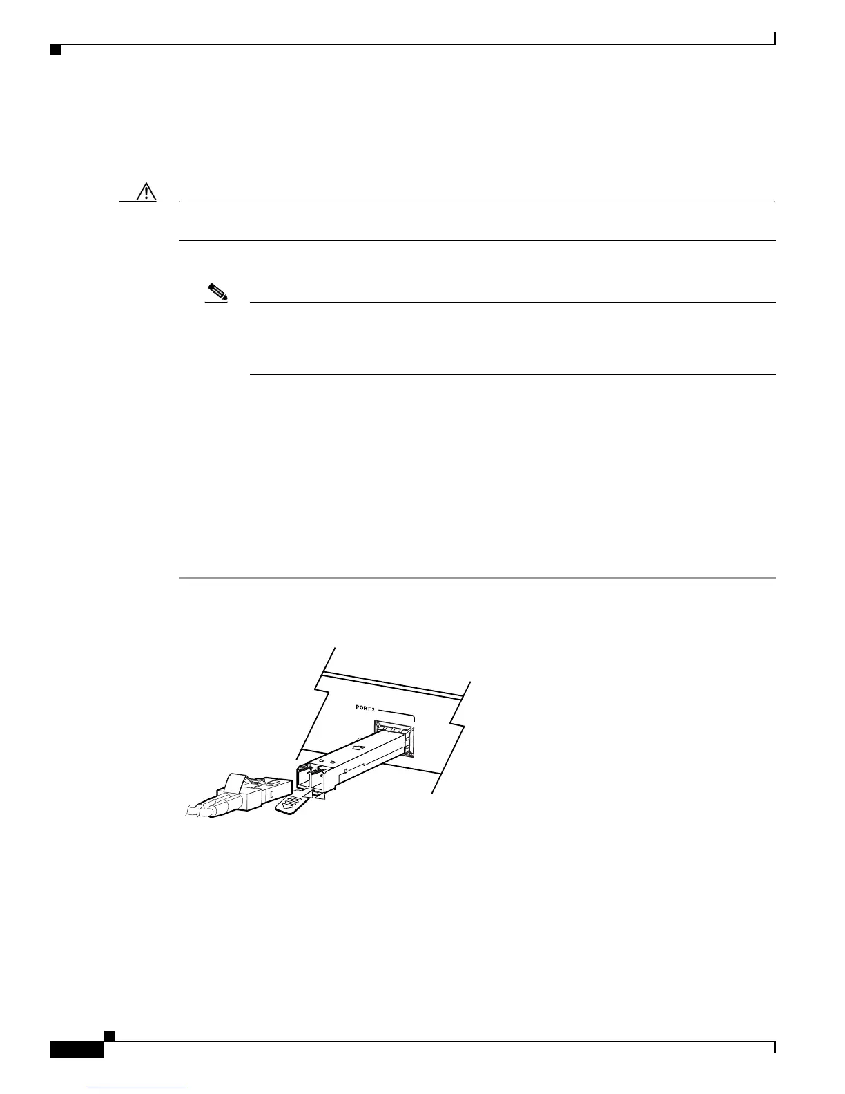
Figure 3-23 Supervisor Engine 720 SFP Uplink Port
91721
SFP module
LC connector
Gigabit Ethernet
UPLINK PORT