4-18
Catalyst 6500 Series Switches Installation Guide
OL-5781-04
Chapter 4 Removal and Replacement Procedures
Removing and Installing the DC-Input Power Supplies
Step 4 Disconnect the DC-input wires from the terminal block (see Figure 4-13 for the 1300 W DC power
supply or Figure 4-14 for the 2500 W DC power supply) in this order:
1. Positive (+)
2. Negative (–)
3. Ground
Note The terminals on the 1300 W DC power supply DC power cable terminal block are labeled (from
top to bottom) +, –, ground. The terminals on the 2500 W DC power supply DC power cable
terminal block are labeled (from top to bottom) –, +, ground.
Step 5 Loosen the captive installation screw on the power supply. (See Figure 4-13 for the 1300 W DC power
supply or Figure 4-14 for the 2500 W DC power supply.)
Caution Use both hands to install and remove power supplies. Each Catalyst 6500 series DC-input power supply
weighs between 22 pounds (10 kg) and 33 pounds (15 kg).
Step 6 Grasp the power supply handle with one hand, and slide the power supply halfway out of the chassis.
Place your other hand underneath the power supply, as shown in Figure 4-15, and slide the power supply
completely out of the chassis. Set the power supply aside.
Step 7 If the power supply bay is to remain empty, install a blank faceplate (Cisco part number 700-03104-01)
over the opening, and secure it with the captive installation screw.
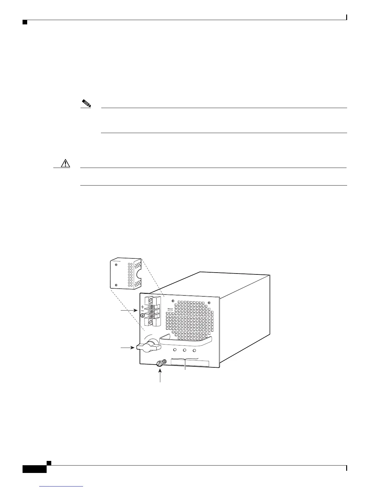
Figure 4-11 DC-Input Power Supply Front Panel (WS-CDC-1300W)
16028
Power
switch
DC power cable
terminal block
Terminal block
cover
INPUT
OK
FAN
OK
OUTPUT
FAIL
I
0
Status LEDs
Captive installation
screw