4-27
Catalyst 6500 Series Switches Installation Guide
OL-5781-04
Chapter 4 Removal and Replacement Procedures
Removing and Installing the DC-Input Power Supplies
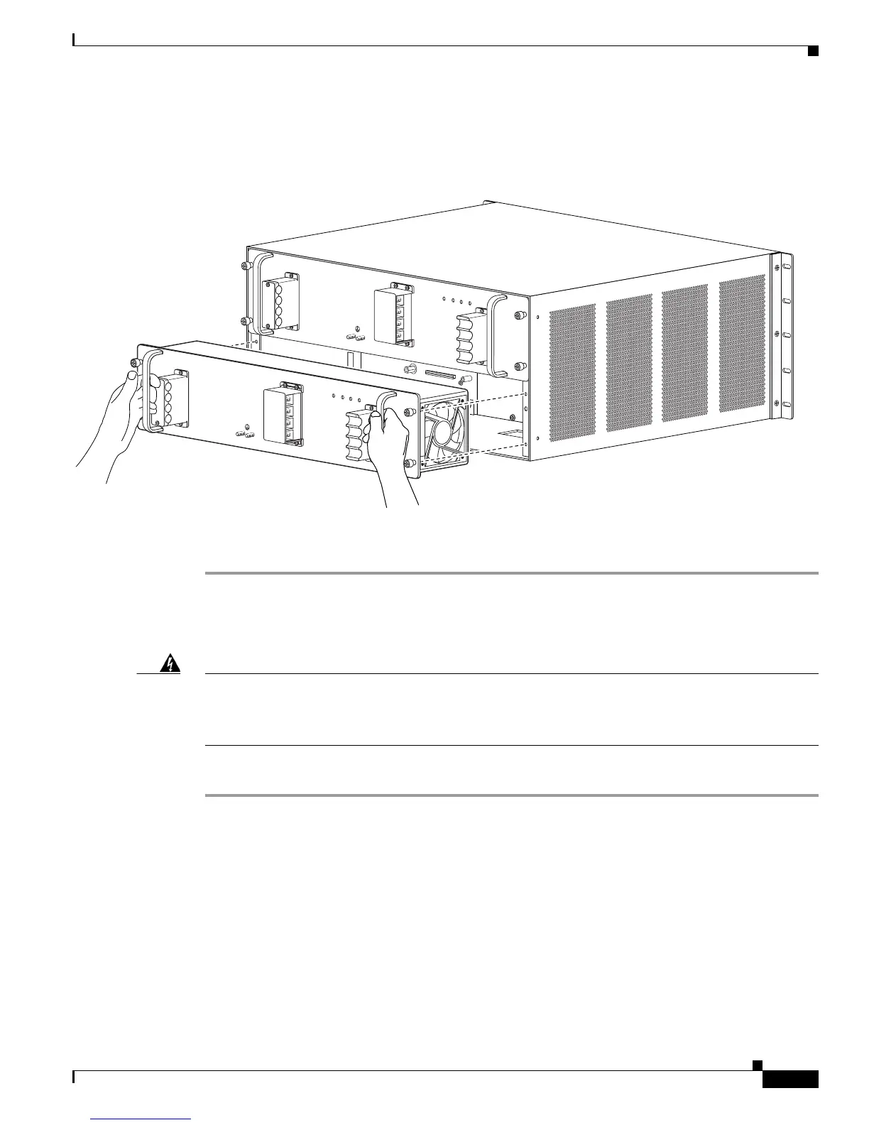
Step 7 Grasp both power supply handles, as shown in Figure 4-19, and slide the power supply completely out
of the chassis.
Figure 4-19 Handling a DC-Input Power Supply
Step 8
If the power supply bay is to remain empty, install a blank power supply filler plate (Cisco part number
700-03104-01) over the opening, and secure it with the captive installation screws.
Installing a 2700 W DC-Input Power Supply
Warning
Before performing any of the following procedures, ensure that power is removed from the DC
circuits. To ensure that all power is removed, locate the circuit breakers or fuses on the DC power
lines that service the DC circuits. Turn OFF the DC power line circuit breakers and remove the DC
power line fuses.
Statement 322
To install a DC-input power supply, follow these steps:
Step 1 Ensure that the system (earth) ground connection has been made. For ground connection installation
instructions, see the “Establishing the System Ground” section on page 3-22.
Step 2 Remove the plastic bag attached to the front panel and put aside. This bag contains two plastic terminal
block barriers, two cable ties, and two cable holder covers.
Step 3 Verify that power is off to the DC circuit on the power supply that you are installing. As an added
precaution, place the appropriate safety flag and lockout devices at the source power circuit breaker, or
place a piece of adhesive tape over the circuit breaker handle to prevent accidental power restoration
while you are working on the circuit.
Grasp both power supply handles, as shown in Figure 4-20. Slide the power supply into the power supply
bay. Make sure that the power supply is fully seated in the bay.
126567
PWR-2700-DC/4
A
L
L
F
A
S
T
E
N
E
R
S
M
U
S
T
B
E
F
U
L
L
Y
E
N
G
A
G
E
D
P
R
IO
R
T
O
O
P
E
R
A
T
IN
G
T
H
E
P
O
W
E
R
S
U
P
P
L
Y
IN
P
U
T
1
O
K
4
8V
-6
0
V
=
4
0
A
IN
P
U
T
2
O
K
48
V
-60
V
=
4
0A
F
A
N
O
K
O
U
T
P
U
T
FA
IL
-V
E-1
-V
E-1
-V
E-2
-VE
-2
A
L
L
F
A
S
T
E
N
E
R
S
M
U
S
T
B
E
F
U
L
LY
E
N
G
A
G
E
D
P
R
IO
R
T
O
O
P
E
R
A
T
IN
G
T
H
E
P
O
W
E
R
S
U
P
P
L
Y
IN
P
U
T1
O
K
4
8
V
-6
0V
=
4
0
A
IN
P
U
T
2
O
K
4
8
V
-6
0
V
=
4
0
A
F
A
N
O
K
O
U
TP
U
T
F
A
IL
PWR-2700-DC/4