4-28
Catalyst 6500 Series Switches Installation Guide
OL-5781-04
Chapter 4 Removal and Replacement Procedures
Removing and Installing the DC-Input Power Supplies
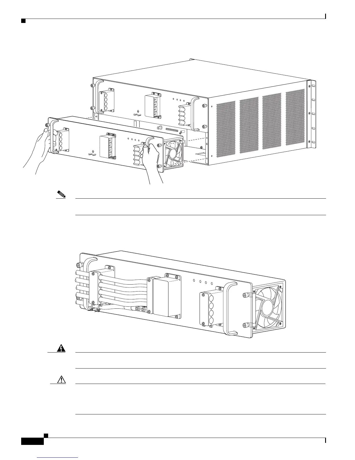
Figure 4-20 Handling the Power Supply
Note This illustration shows the terminal block barriers and the terminal block guards that are attached to
them.
Step 4 Tighten the power supply captive installation screws. (See Figure 4-21.)
Figure 4-21 Power Supply Captive Installation Screws
Warning
Power supply captive installation screws must be tight to ensure protective grounding continuity.
Statement 289
Caution For proper 2700 W DC-input redundant power configuration, the two pairs of input wires (INPUT 1 and
INPUT 2) for one 2700 W DC-input power supply must come from the same battery system (A feed);
the two pairs of input wires for the second 2700 W DC-input power supply must come from another
battery system (B feed).
126567
PWR-2700-DC/4
A
L
L
F
A
S
T
E
N
E
R
S
M
U
S
T
B
E
F
U
L
L
Y
E
N
G
A
G
E
D
P
R
IO
R
T
O
O
P
E
R
A
T
IN
G
T
H
E
P
O
W
E
R
S
U
P
P
L
Y
IN
P
U
T
1
O
K
4
8
V
-6
0
V
=
4
0A
INP
U
T2
O
K
4
8V
-6
0
V
=4
0
A
F
A
N
O
K
O
U
TP
U
T
FA
IL
-V
E-1
-VE-1
-V
E-2
-V
E-2
A
L
L
F
A
S
T
E
N
E
R
S
M
U
S
T
B
E
F
U
L
L
Y
E
N
G
A
G
E
D
P
R
IO
R
T
O
O
P
E
R
A
T
IN
G
T
H
E
P
O
W
E
R
S
U
P
P
L
Y
IN
P
U
T
1
O
K
48
V
-6
0
V
=
4
0
A
IN
P
U
T
2
O
K
4
8
V
-6
0
V
=
4
0
A
F
A
N
O
K
O
UT
P
U
T
F
A
IL
PWR-2700-DC/4
132220
IN
PU
T
1
O
K
48V
-60V
=40A
IN
P
U
T2
O
K
48V
-60V
=40A
FA
N
O
K
O
U
TP
U
T
FA
IL
ALL FASTENERS MUST BE FULLY ENGAGED
PRIOR TO OPERATING THE POW
ER SUPPLY
PWR-2700-DC/4