12-12
Cisco ONS 15454 Reference Manual, R7.0.1
OL-9217-01
Chapter 12 SONET Topologies and Upgrades
12.2 12.2.4 BLSR Application Example
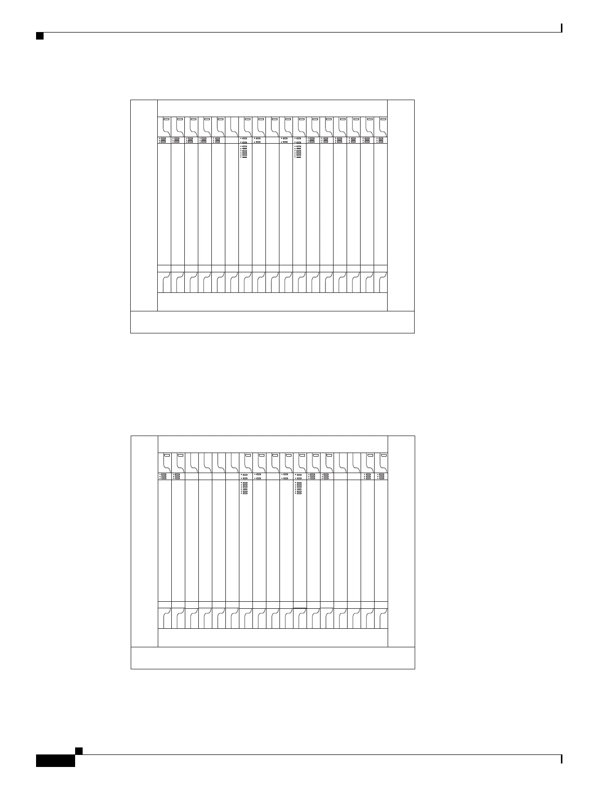
Figure 12-9 Shelf Assembly Layout for Node 0 in Figure 12-8
Figure 12-10 shows the shelf assembly layout for the remaining sites in the ring. In this BLSR
configuration, an additional eight DS-3s at Node IDs 1 and 3 can be activated. An additional four DS-3s
can be added at Node 4, and ten DS-3s can be added at Node 2. Each site has free slots for future traffic
needs.
Figure 12-10 Shelf Assembly Layout for Nodes 1 to 4 in Figure 12-8
DS1-14
DS1-14
DS1N-14
DS1-14
DS1-14
OC48
TCC2/TCC2P
Cross Connect
AIC-I (Optional)
Cross Connect
TCC2/TCC2P
OC48
OC3
OC3
DS3-12
DS3-12
Free Slot
134608
DS1-14
DS1-14
TCC2/TCC2P
Cross Connect
AIC-I (Optional)
Cross Connect
TCC2/TCC2P
Free Slot
Free Slot
OC48
DS3-12
DS3-12
Free Slot
Free Slot
Free Slot
OC48
Free Slot
134605

 Loading...


