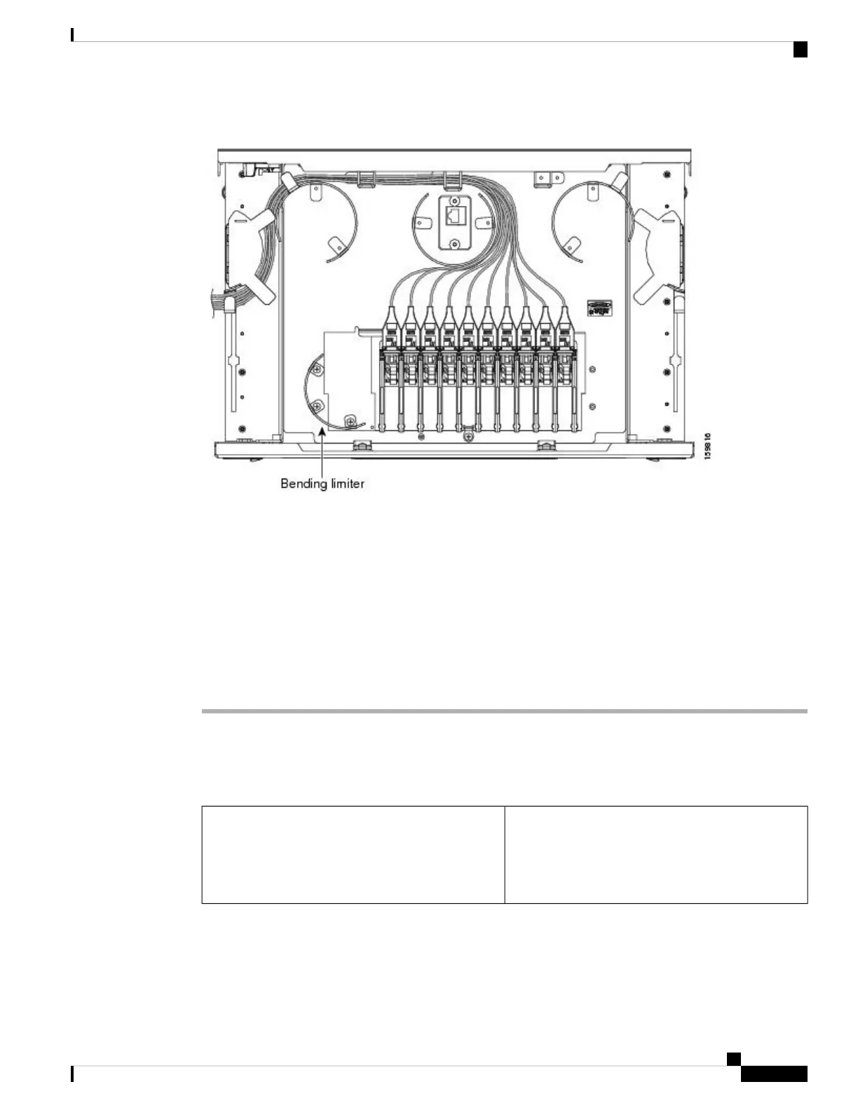
Figure 11: 40-Channel Patch Panel Tray, Top View
Step 2 Slide each of the ten LC-port adapter packs upward.
Step 3 Unscrew the two screws in the bottom left bending limiter and remove the bending limiter.
Step 4 Remove the single screw below the center of the patch panel to free the patch panel hardware.
Step 5 Slide the patch panel to the left, and reinstall the screw below the center of the patch panel.
Step 6 Install the bending limiter to the right of the patch panel by installing the two screws.
Step 7 Carefully route all of the MPO cables around the bending limiter and out the exit on the right side of the patch
panel tray.
Step 8 Slide each of the ten LC-port adapter packs downward.
Step 9 Return to your originating procedure (NTP).
DLP-G428 Installing Fiber-Optic Cables from the 40-WSS-C/40-WSS-CE and
40-DMX-C/40-DMX-CE Cards to the 40-Channel Patch Panel Tray
This task describes how to route fiber-optic cables
from 40-WSS-C/40-WSS-CE and
40-DMX-C/40-DMX-CE cards in an expanded
ROADM, terminal, or hub node to the 40-channel
(80-port) patch panel tray (15454-PP-80).
Purpose
Turning Up a Node
45
Turning Up a Node
DLP-G428 Installing Fiber-Optic Cables from the 40-WSS-C/40-WSS-CE and 40-DMX-C/40-DMX-CE Cards to the 40-Channel Patch Panel Tray

 Loading...


