Onsite or remoteOnsite/Remote
Provisioning or higherSecurity Level
Procedure
Step 1 In the node view, click Provisioning > WDM-ANS > OTDR > Side > Baseline Thresholds.
Step 2 From the OTDR Position drop-down list, select the port to be configured with threshold values.
Step 3 Equipment Insertion Loss for OTDR (Display only) Displays the sum of insertion loss caused by the
amplifiers and patchcords for OTDR port in each direction.
Step 4 Choose a sector from the Sector drop-down list.
The default Loss Threshold and Reflection Threshold values for the corresponding sector are displayed in
CTC. You can also configure these thresholds.
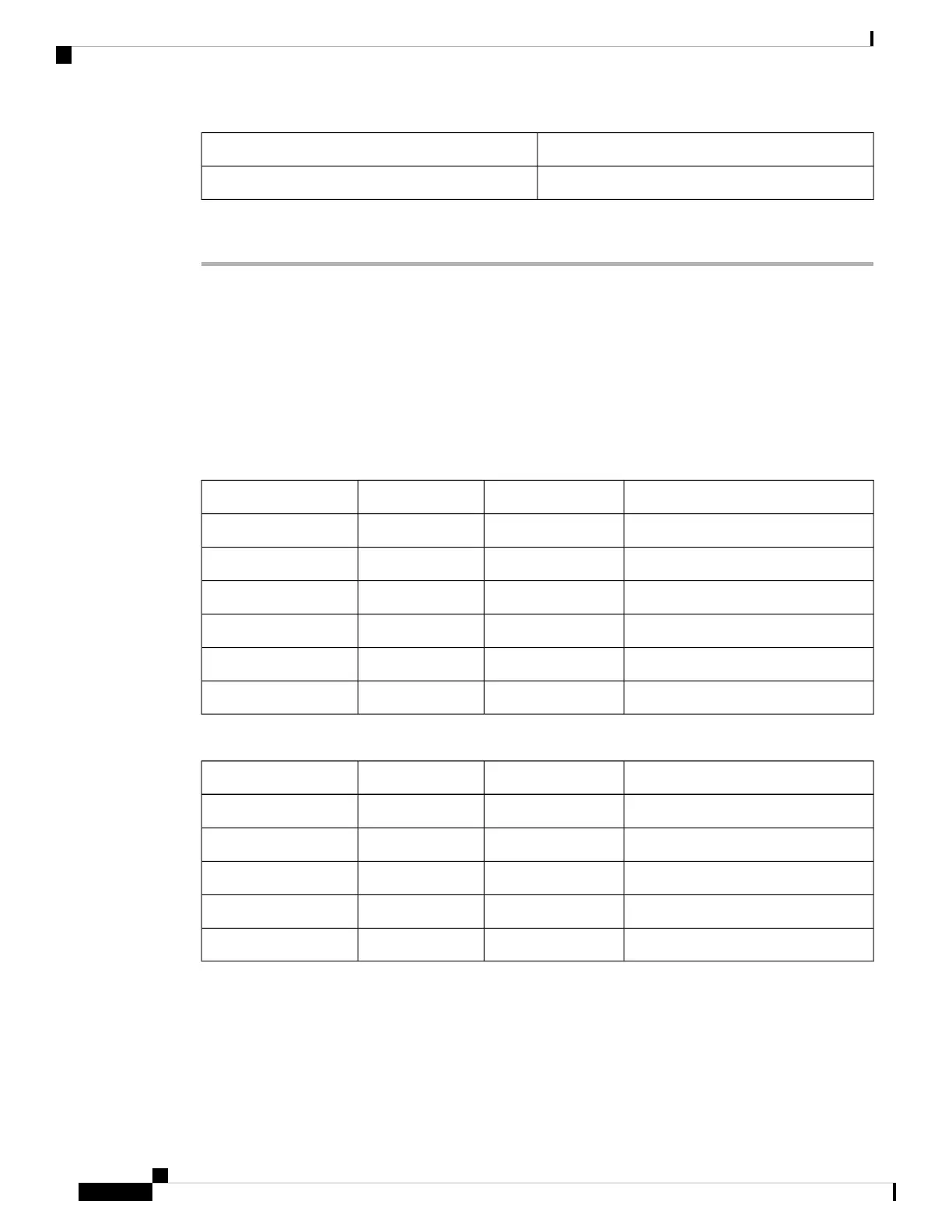
Table 10: Loss Threshold Value Range
Default (dB)Max (dB)Min (dB)Sector
0.150.1Zone #1
0.1550.15Zone #2
0.2550.25Zone #3
0.550.5Zone #4
0.2550.25Expert Mode
0.2550.25Auto Scan
Table 11: Reflection Threshold Value Range
Default (dB)Max (dB)Min (dB)Sector
2202Zone #1
2202Zone #2
2202Zone #3
2202Zone #4
2202Expert Mode
The threshold values are used to compare events reported in the Base Scan column and Last Scan
column in the table available at Maintenance > DWDM > OTDR. If the difference exceeds the
threshold, alarms are raised.
Note
The following alarms are raised when the scan results for Insertion Loss and Reflection Loss exceeds the
threshold values:
Turning Up a Node
86
Turning Up a Node
DLP-G784 Configuring Threshold Values for OTDR Scan

 Loading...


