4023074 Rev B Model D9858 Advanced Receiver Transcoder Installation and Operation Guide 3-13
Connecting an External Alarm System
Connector for an External Alarm System
The D9858 Advanced Receiver Transcoder is equipped with a connector labeled
Cue Tone/Relay which provides alarm relay outputs for remote alarm signaling.
This connector provides Cue Tone, Cue Trigger and Alarm relay functionality. See
Pin allocation, RS-232 Data connector, page 3-14 for more information on Cue
Tone and Cue Trigger equipment connections. These outputs are user-configurable
via the Setup Menu on the front panel.
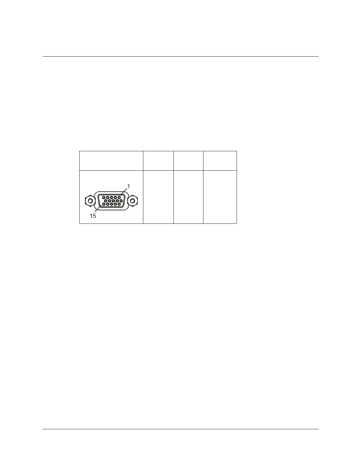
The Alarm output connector is a 15-pin sub-D female connector. The following
diagram shows the connector and the pin allocation table for the Alarm output pins.
1. Connect the cable from the external alarm system to the alarm connector.
Connector Normally
closed pin
Common
pin
Normally
open pin
11 10 15
 Loading...