Page 34 FF6300 Operating Manual
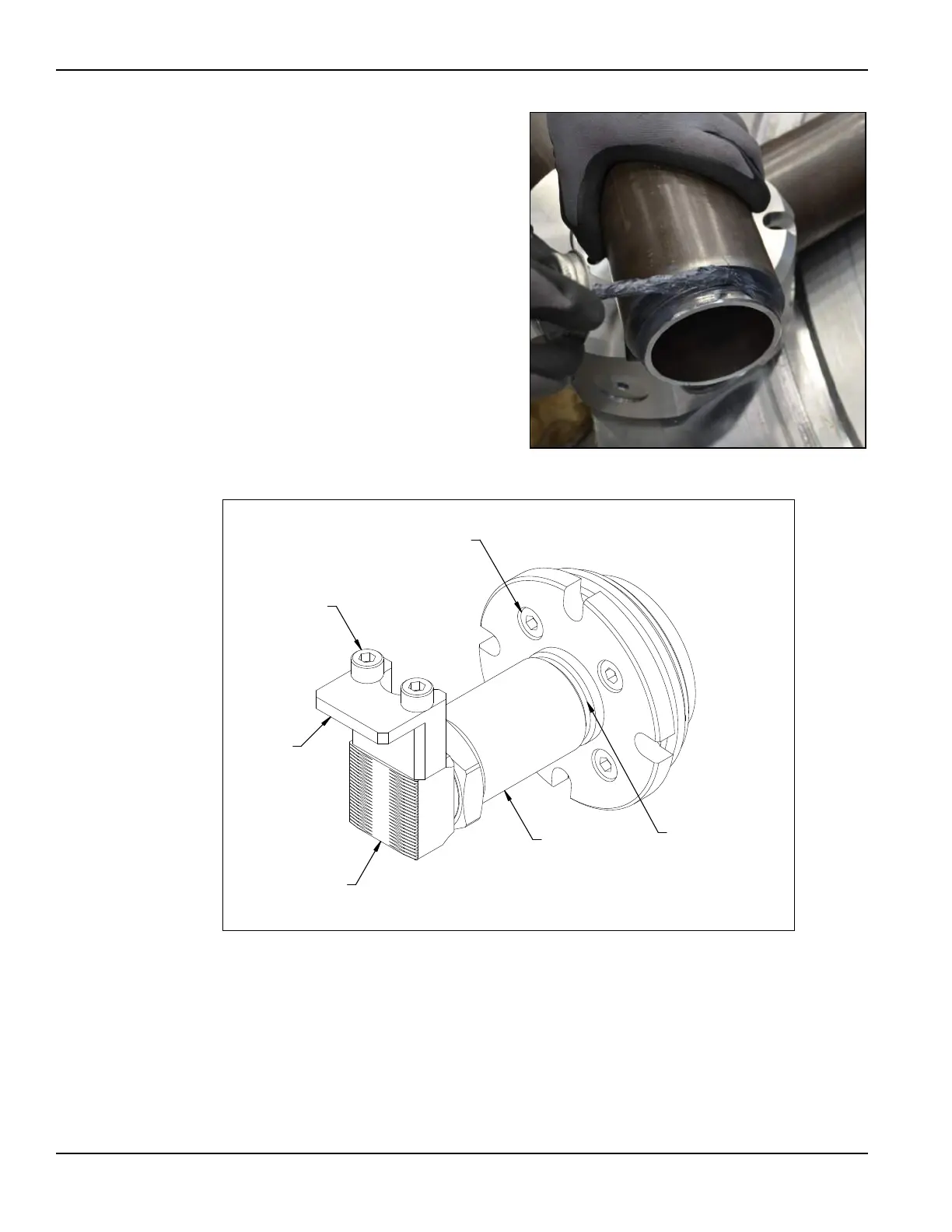
3. Apply the anti-seize com-
pound (provided in the tool kit)
to the threads and contacting
faces of each leg section.
4. Screw the leg sections together.
Adjust the leveling jaws even
with the base and check that the
setup fingers are installed on
the leveling jaw.
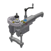
FIGURE 3-13. DETAIL OF ID CHUCK LEGS
5. Use a simple scale to roughly center the jacking screws. About 0.1" (2.5mm)
clearance will allow insertion of the chuck while maintaining sufficient contact
between the setup finger and the flange face.
6. Install the ID chuck into the bore of the flange.
7. Using the short-handled 46mm wrench provided in the tool kit, tighten the
jacking screws evenly.
FIGURE 3-12. APPLYING ANTI-SEIZE COMPOUND
SETUP
FINGER
CAPTIVE M8
SCREWS
LOCKING
SCREWS
LEVELING
JAW
FULL EXTENSION
GROOVE
JACKING
SCREW
PP:5(1&+