P/N 80679, Rev. 10 Page 35
Do not over tighten, as this
could bind the leveling feet
during leveling. Check that the
setup fingers are seated evenly.
Do not extend the jacking feet
past the full-extension groove in
the threaded screw (Figure 3-
13 on page 34). If needed, add
additional leg sections to
minimize the length of the threaded jacking screw that is exposed.
8. After securely attaching the machine to the flange, attach a dial indicator to the
turning arm.
9. Check that power to the machine drive is isolated and locked out.
10. Using the dial indicator, indicate the workpiece surface for level while
manually rotating the machine.
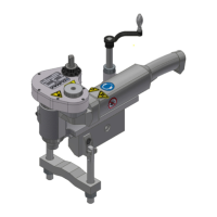
• To manually rotate the pneumatic machine, insert a 10-mm hex wrench in
the hex opposite the motor or push on the end of the turning arm.
• To manually rotate the
hydraulic machine, use the
cross-connection hose
supplied with the machine
to connect the #1 and #2
port hoses. Insert a 10 mm
hex wrench in the hex
opposite the motor or push
on the end of the turning
arm.
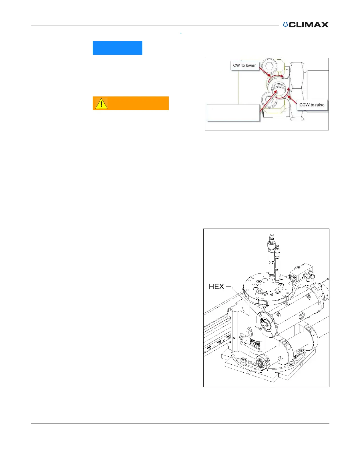
11. Level the machine by turning
the leveling screws in each of
the leveling feet with the dial
indicator close to leveling
adjustment (Figure 3-6 on
page 29).
12. Reposition the dial indicator
to check machine centering.
13. Center the machine by adjust-
ing opposing pairs of jacking
feet.
Leveling screw
(10mm
Hex wrench)
FIGURE 3-14. ADJUSTING THE SETUP FINGERS
FIGURE 3-15. LOCATION OF THE 10-MM HEX FOR MANUAL
ROTATION OF THE MACHINE