(2.) The UUT will power on and begin the
initialization sequence.
(3.) After initialization, the PMR & RCDU panels
will look similar to Figure 8-2 Knob Test 1
(found on the next page). *
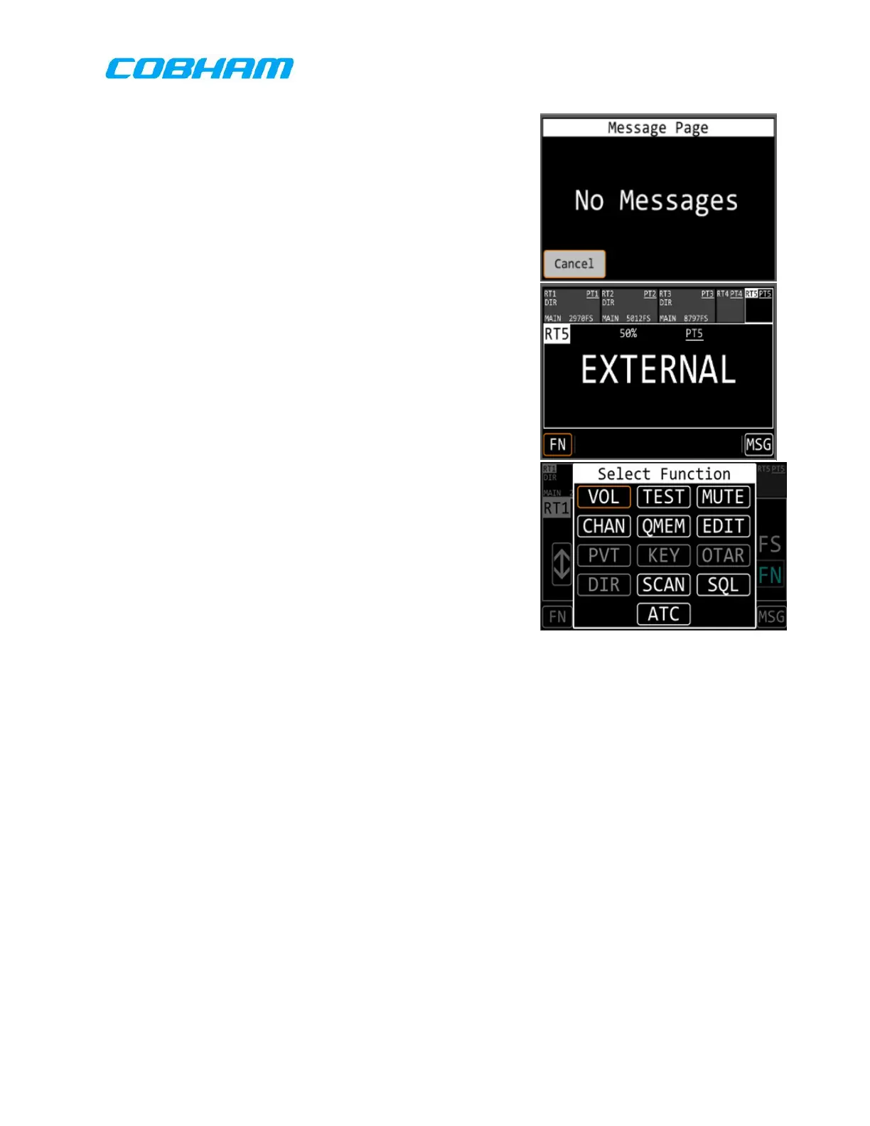
(4.) Touch the “MSG’ box in the lower right
corner of the touchscreen display.
(5.) Verify that the “Message Page” window
appears, similar to Figure 8-1 RCDU Menus.*
(6.) Touch the “Cancel” box in the lower left hand
corner of the touchscreen display.
(7.) Verify that the default display shown in Figure
8-2 Knob Test 1 appears.
(8.) Touch the “RT5” box in the upper right hand
corner of the touchscreen display.
(9.) Verify that the “EXTERNAL” window appears
over the display as shown in Figure 8-1.*
(10.) Touch the “RT1” box in the upper left hand
corner.
(11.) Verify that the default display shown in
Figure 8-1 appears.*
(12.) Touch the “FN” box in the lower left-hand
corner of the touchscreen display.
(13.) Verify that the “Select Function” window
appears over the display as shown in Figure
8-1.*
(14.) Press the “HOME” button.
(15.) Verify that the default display shown in Figure 8-1 appears.*
(16.) If continuing to the next section, skip this step. Press and hold the On/OFF, left
inner knob until the UUT turns off. Turn off the UUT power supply.
8.6.1.2 Control Surfaces and Knob Verification
All of the operations described below are carried out on the RCDU only. If continuing
from steps above, proceed to step 5.
(1.) Turn on the UUT Power Supply and verify that the current is below 4.5 A. If the
RCDU does not power on, press the lower left inner knob.*
(2.) The UUT will power on and begin the initialization sequence.
(3.) After initialization, press the “HOME” button on both front panels.
(4.) The PMR & RCDU panels will look similar to Figure 8-1.
 Loading...