This document contains proprietary information,
see proprietary statement on first page.
NOTE 4: The RT-7000 is designed to be a VOICE radio only. It does not have data capability and
therefore the audio from an ACARS modem shall not be connected to the RT-7000 microphone
input and the RT-7000 shall not be used to send or receive ACARS data.
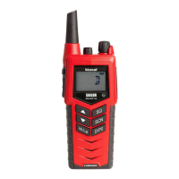
Mic 1 Hi
Mic 1 Lo
Audio 1 Hi
Audio 1 Lo
PTT 1
(Example) EMERG MODE
Backshell
Mic 1 Hi
Mic 1 1 Lo
Audio 1 Hi
Audio 1 Lo
PTT 1
Mic Mode
Backshell
69
70
1
2
33
76
Audio Panel
RT-7000 PMR/RMR
J101
Audio Panel channel assignments are for example only
Figure 7-7: RT-7000 MIC BIAS Configuration
NOTE 1 : The diagram above in Figure 7-7: RT-7000 MIC BIAS Configuration, shows the proper way to
enable MIC BIAS on channel 1. Note both pins 76 and pins 70 are pulled to ground.
Mic Bias Natively Avialable
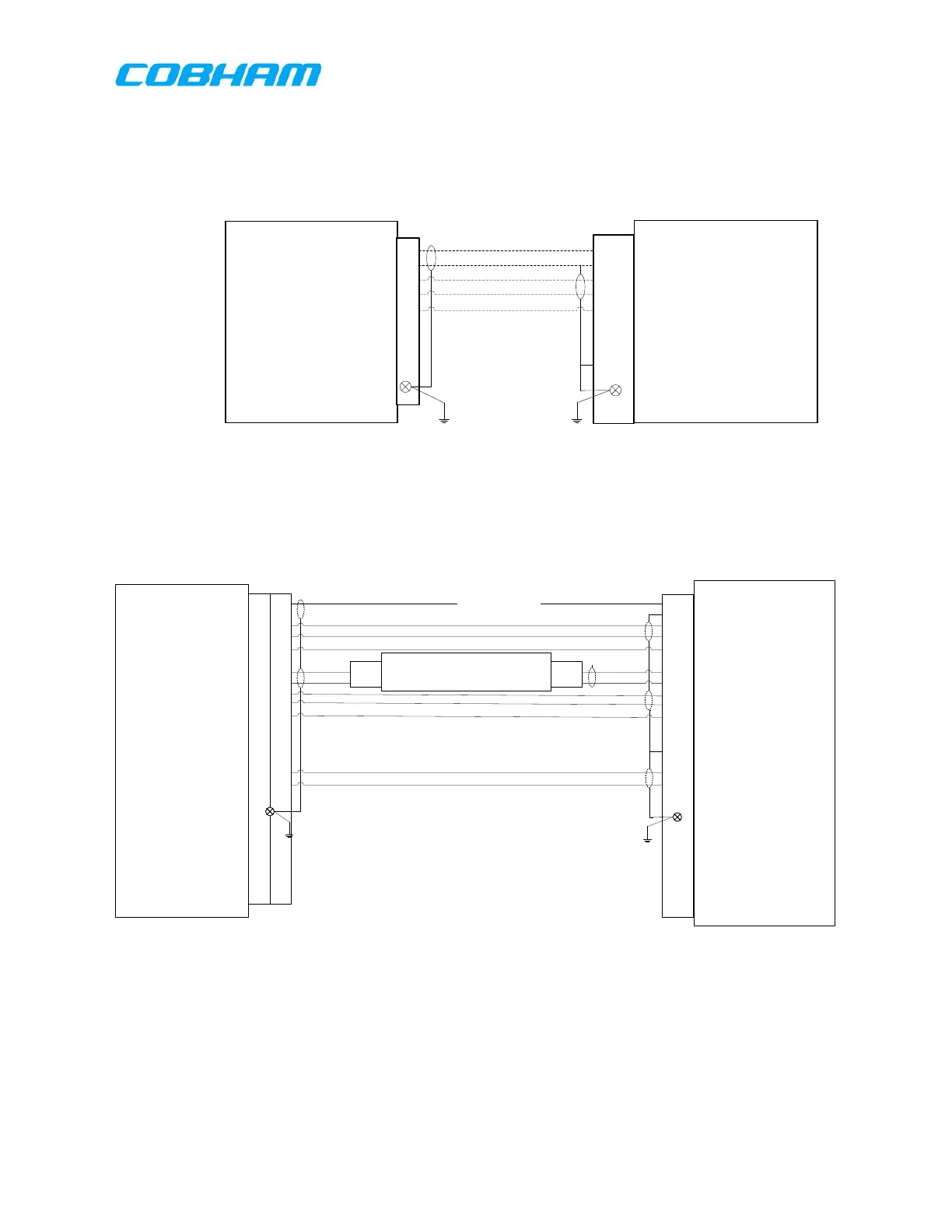
Mic 1 Hi
Mic 1 1 Lo
Audio 1 Hi
Audio 1 Lo
PTT 1
Mic 2 Hi
Mic 2 Lo
Audio 2 Hi
Audio 2 Lo
PTT 2
Mic Mode
Combined Audio Hi Out
Combined Audio Lo Out
Backshell
69
70
1
2
33
27
28
48
49
32
76
3
4
RT-7000 PMR
J101
Model 247: Mixer1
Mixer 1, IN 1 HI Mixer 1, OUT 1 HI
Mixer 1, IN 1 LO Mixer 1, OUT 1 LO
1
16
35
34
P40 P40
Model 247 GND
AUDIO PANEL
Mic 1 Hi
Mic 1 Lo
Audio 1 Hi
Audio 1 Lo
PTT 1
Mic 2 Hi
Mic 2 Lo
Audio 2 Hi
Audio 2 Lo
PTT 2
(Example) EMERG MODE
(Example) Flight Recorder Hi
(Example) Flight Recorder Lo
Backshell
Audio Panel channel assignments are for example only
Figure 7-8: RT-7000 MIC BIAS Configuration Other Channels
NOTE 2: The diagram above in Figure 7-8: RT-7000 MIC BIAS Configuration Other Channels shows how
to wire in a dynamic MIC BIAS amplifier on the MIC line that can provide MIC bias on channels 2-5.
These commodities, technology or software are controlled in accordance with the United States Export Administration Regulations, Export Classification
Control Number (ECCN) EAR99. When exporting, diversion contrary to U.S. law is prohibited.
 Loading...