This document contains proprietary information,
see proprietary statement on first page.
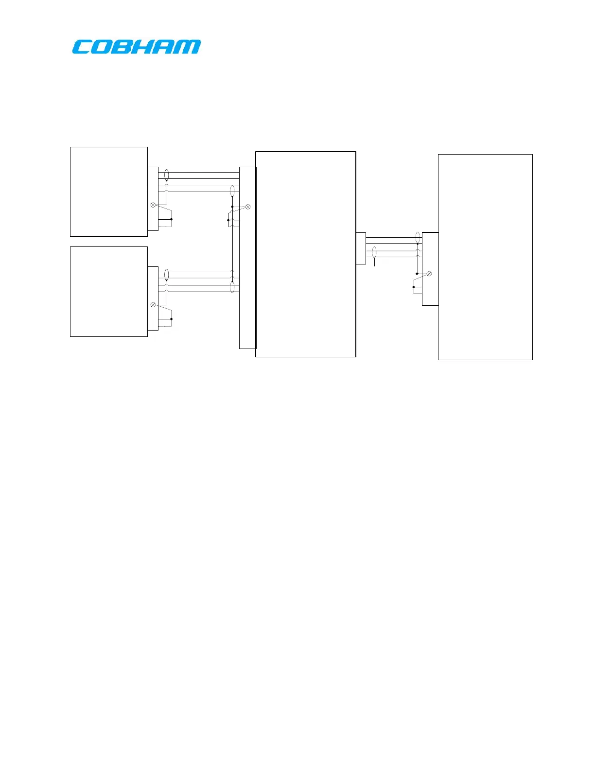
9.7 PMR / RMR / RCDU CONFIGURATION SETTINGS
This section will instruct you on the software configurations required on the PMR, RMR, and RCDU to
control or display information from other devices. In the example shown below we can see a complex
system that in volves two RMRs interfaced through the Primary RCDU, then a secondary RCDU.
NOTE: The system will not function properly until all modules are programmed accordingly.
J101
M2J1
J101
RCDU 2 (Optional)
RS4852 HI
RS4852 LO
RS4851 HI
RS4851 LO
Backshell
Ground
Ground
19
20
15
16
66
73
M2J1
15
16
19
20
M2J1
36
37
54
55
66
73
RT-7000 RMR 2
(Optional)
Remote Radio Control TX HI
Remote Radio Control TX LO
Remote Radio Control RX HI
Remote Radio Control RX LO
Backshell
Ground
Ground
54
55
36
37
66
73
8
9
6
7
RCDU 1
Remote Radio Control1 RX HI
Remote Radio Control1 RX LO
Remote Radio Control1 TX HI
Remote Radio Control1 TX LO
Backshell
Ground
Ground
RS4851 HI
RS4851 LO
RS4852 HI
RS4852 LO
Remote Radio Control2 RX HI
Remote Radio Control2 RX LO
Remote Radio Control2 TX HI
Remote Radio Control2 TX LO
RT-7000 RMR 1
Remote Radio Control TX HI
Remote Radio Control TX LO
Remote Radio Control RX HI
Remote Radio Control RX LO
Backshell
Ground
Ground
36
37
54
55
66
73
To M2J1
Backshell and
pins 66, 73
Figure 9-11: RT-7000 Dual RMR and Dual RCDU
9.7.1 RMR (OR PMR) 1 & 2 PROGRAMMING
This section will cover the programming required for the RMRs shown in Figure 9-13: Primary RCDU
Configratin Screen with dual RMR and dual RCDU. As seen in the figure below the port on the RMR must
be configured so the UART protocol is set to RS-422, and the UART Baud Rate is 115200. This can be
seen highlighted in Orange.
These commodities, technology or software are controlled in accordance with the United States Export Administration Regulations, Export Classification
Control Number (ECCN) EAR99. When exporting, diversion contrary to U.S. law is prohibited.
 Loading...