This document contains proprietary information,
see proprietary statement on first page.
Antenna Tuner 2 TX+ (P1-C) (Optional)
Aircraft Backlighting Ground Reference (PMR
only)
Aircraft Backlighting Control (PMR only)
External Radio 1 Jack PTT (Optional)
External Radio 1 Jack PTT Ground (Optional)
External Radios TX Interlock
Antenna Switching Unit 3
Control
Antenna Switching Unit 3 J1-2 (Optional)
Audio Panel Out Hi (typically Channel 1)
Audio Panel Out Lo (typically Channel 1)
External Radio 2 Jack PTT Ground (Optional)
External Radio 1 Jack PTT (Optional)
Antenna Switching Unit1
Control
Antenna Switching Unit 1 J1-2 (Optional)
Antenna Switching Unit 2
Control
Antenna Switching Unit 2 J1-2 (Optional)
Direct Microphone interfacing mode
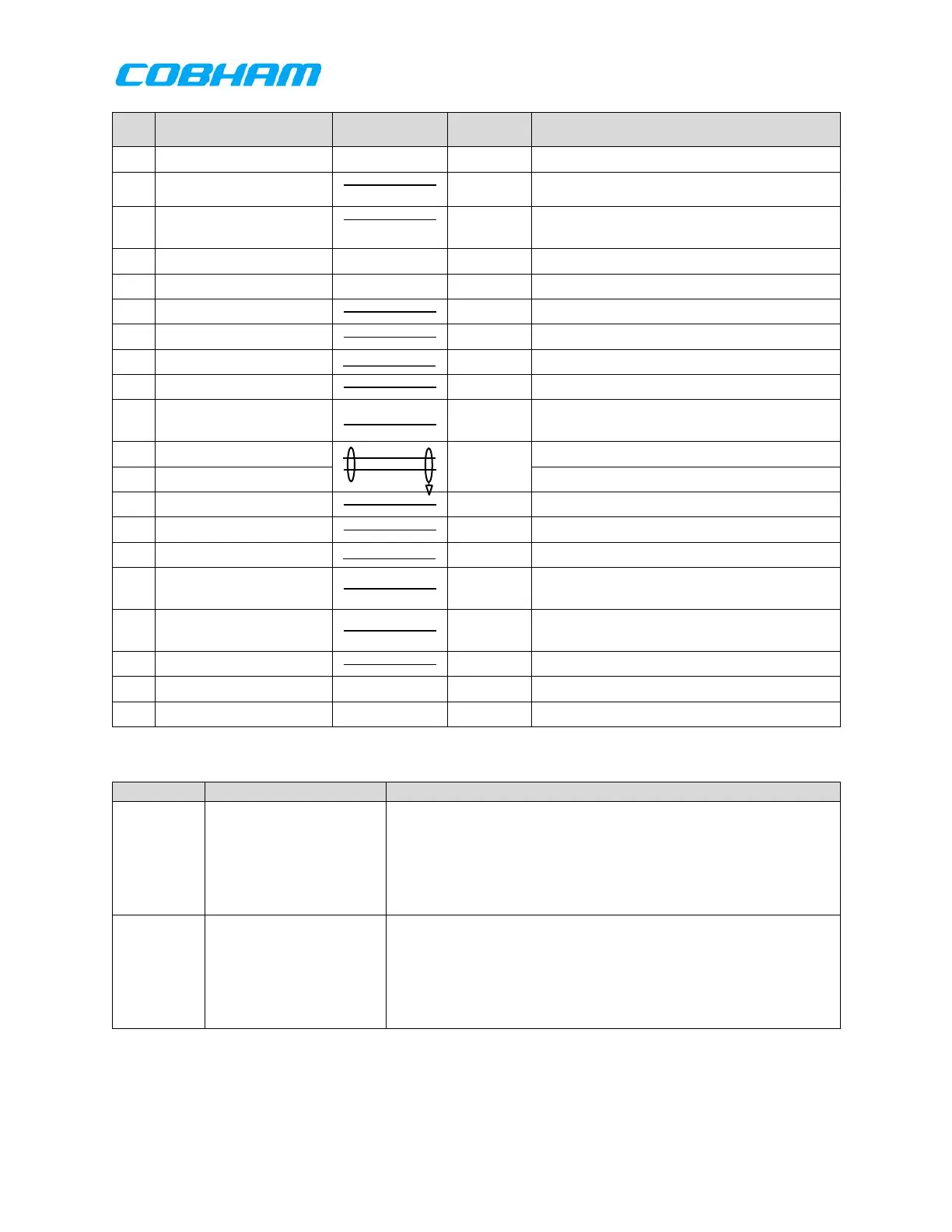
Table 7-1: RT-7000 PMR/RMR System Interface Connector J101
These pins provide an audio output to the audio system from
Transceiver 1. Assignment of a transceiver to Audio 1 is a
programmable option, default is to the transceiver in slot 1.
This output is capable of adjustment from 2.5Vrms ±0.25 Vrms
(10mW) to 7.75 Vrms ±0.25 Vrms (100mW) into a 600 Ω load
(except as noted)
Cabin Voice Recorder
(CVR) Audio Out Hi/Lo
The CVR Audio output, (Signal Name: Audio Output 6), is a
user selectable audio output port. This output is configured in
the ICT and allows multiple audio paths to be combined into a
single output source from the RT-7000 PMR/RMR. The
combined audio levels are determined by the selected radio’s
audio level. Please see section 9.3.3 for further details.
These commodities, technology or software are controlled in accordance with the United States Export Administration Regulations, Export Classification
Control Number (ECCN) EAR99. When exporting, diversion contrary to U.S. law is prohibited.
 Loading...