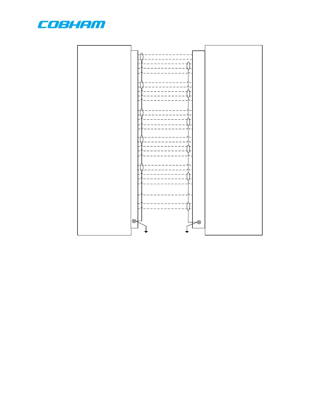
Figure 7-6: RT-7000 PMR/RMR Interconnections – Standard Audio Configuration
NOTE 1: The Figure 7-6: RT-7000 PMR/RMR Interconnections – Standard Audio Configuration shown
above is an example installation of the RT-7000 PMR/RMR with an audio control panel. This
configuration shown has all five Audio/Mic/PTT paths routed directly to five audio control panel
paths. The audio paths and radio paths are configurable on the RT-7000 PMR/RMR using the ICT
tool. Please see the ICT section 9 for further information.
NOTE 2: The RT-7000 mic bias is available only on audio 1. If mic bias is required on another audio line,
an external mic bias adapter is required. The MIC MODE can also be used as an EMER mode to
enable MIC bias if the audio panel is switched to emergency and pin 76 and pin 70 gets pulled to
ground. The RT-7000 Mic Mode, pin 76, can be configured to facilitate a direct headset interface
for the RT-7000 PMR/RMR. If RT-7000 Mic Mode will be enabled, Mic Mode will then apply a bias
voltage to the Mic 1 Hi/Lo path on pins 69 and 70 hence enabling a direct headset connection.
NOTE 3: The CVR Audio path, pins 3 and 4 on the RT-7000 PMR/RMR, is a configurable audio output. In
the example shown above, the audio panel features a Flight Recorder Input, and the CVR Audio is
then connected to provide an audio output to this flight recorder. The Combined Audio is
configurable in the ICT tool to select which channels the combined audio will output. Please see
the ICT section 9.3.3 for further information.
These commodities, technology or software are controlled in accordance with the United States Export Administration Regulations, Export Classification
Control Number (ECCN) EAR99. When exporting, diversion contrary to U.S. law is prohibited.
 Loading...