This document contains proprietary information,
see proprietary statement on first page.
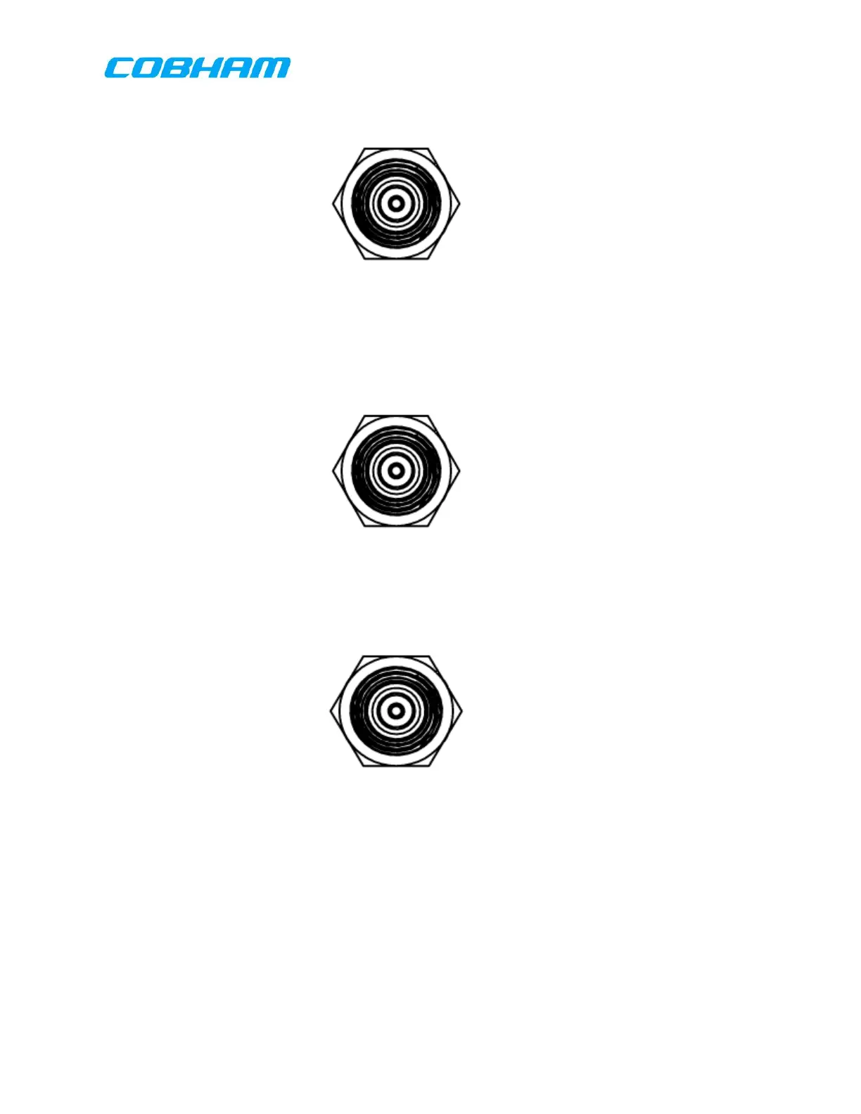
50 Ω TNC
(3) NC
NC connects the antenna switching unit to the low split antenna. NC is a TNC
connector with mating connector Amphenol P/N 122393 (for LMR400 Coax) or
equivalent.
50 Ω TNC
(4) NO
NO connects the antenna switching unit to the high split antenna. NO is a TNC
connector with mating connector Amphenol P/N 122393 (for LMR400 Coax) or
equivalent.
50 Ω TNC
D FC-570/FC-580/FC-5000 Antenna Tuning Unit Wiring Considerations
Interconnections between the RT-7000 PMR , antenna tuner, and antenna are
identical for the FC-570/AT-570, and FC-5000/AT-5000. See Figure 7-12.
(1) J1
The J1 connector provides tuning information between the RT-7000 PMR and the
tuner. J1 is a KPTO2E-14-19P, 19 pin connector, with aircraft mating connector:
KPT06E-14-19S
These commodities, technology or software are controlled in accordance with the United States Export Administration Regulations, Export Classification
Control Number (ECCN) EAR99. When exporting, diversion contrary to U.S. law is prohibited.
 Loading...