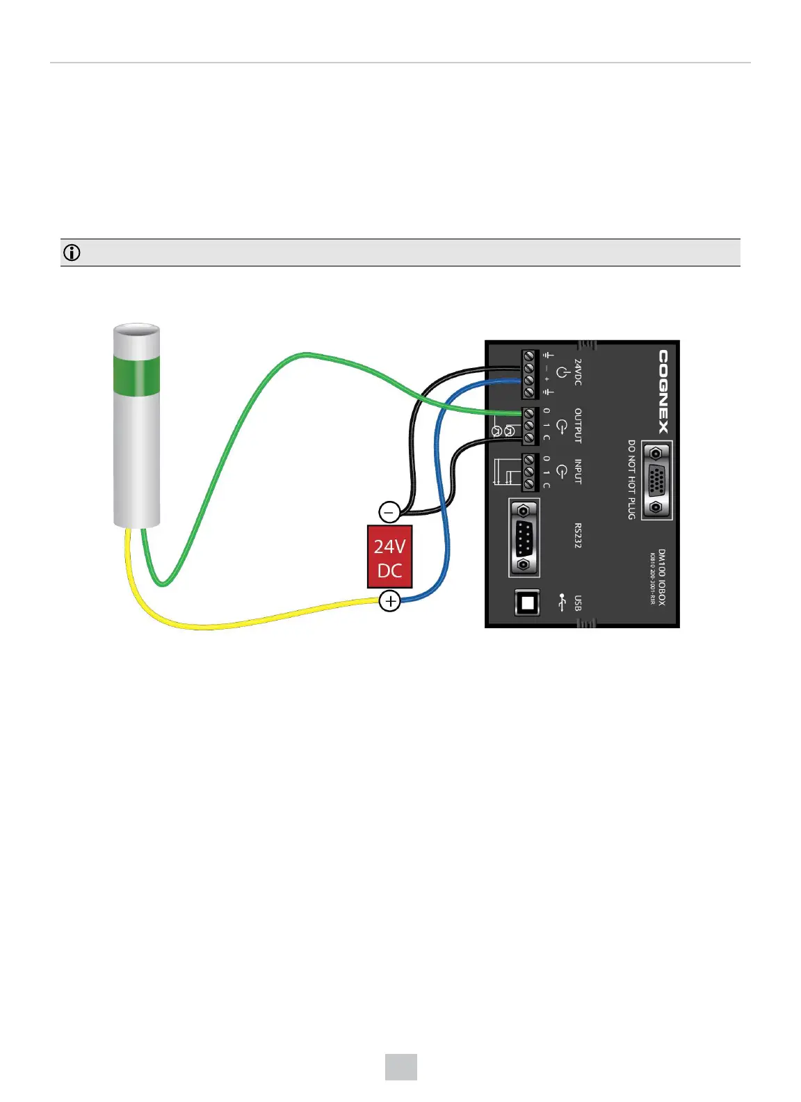
1. Power: 5-24 VDC, 2.5 W peak. Connect either ground pin to chassis ground.
2. Discrete output: Opto-isolated, current source or sink, depending on wiring; must connect logical ground to
common. Outputs are opto-isolated and protected against reverse polarity. Max current is 50 mA @ 24 VDC.
Output 1 is used for external illumination control by default.
3. Trigger input: Opto-isolated, polarity-independent, current source or sink; have reference to a separated
common signal. Work with ±15-30 V. Input 0 is dedicated trigger line.
4. Communication:RS-232 serial port and USB port.
Note: You must use a null modem cable when connecting the Basic I/O Module to a PC’s RS-232 serial port.
Output Wiring Example
98
Electrical Information