6-2 Removal and Replacement Procedures - Minitower
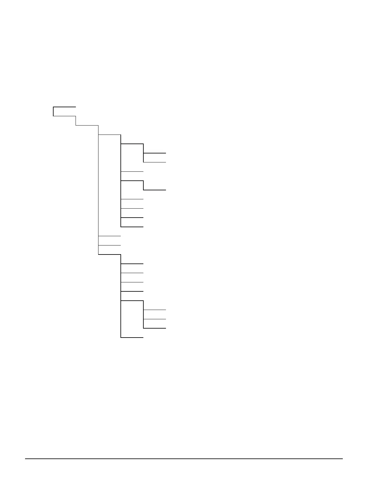
6.2 Disassembly Sequence Chart
Use the chart below to determine the disassembly sequence for removing components from the
computer.
6.4 Computer Feet
6.5 Cable Lock
6.6.1 Access Panel
6.7 Riser Brace
6.8 Expansion Board
6.9 Expansion Board Guide
6.10 Riser Board
6.11 Speaker
6.12.1 Memory Module
6.13 System Board
6.12.2 Microprocessor
6.12.3 Cache Memory (Pentium only)
6.12.4 System Board Graphics Memory Module Upgrade
6.14 Replacement Battery (if full-length expansion board installed)
6.14 Replacement Battery (if short expansion board installed)
6.15 ISA Option Board Retainer
6.16.1 Front Bezel
6.6.2 J Hood
6.16.2 Power Button
6.16.3 Bezel Blank
6.16.4 Compaq Logo
6.17.1 Power Supply Switch Assembly
6.17.2 Power Supply
6.18 LED Cable
6.19.1 3.5-in Drive Bays
6.19.2 5.25-in Drive Bays