2022_05 SAM_EN | 01 13
2.7 Integration of the subsystem in a charging column
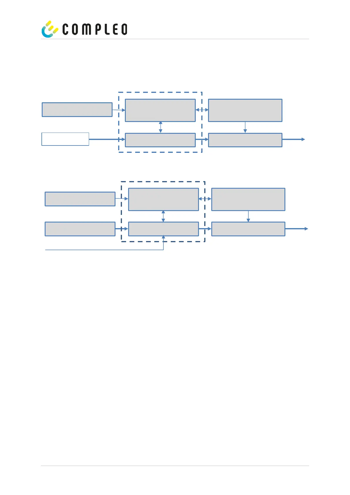
With the subsystem, it is possible to carry out all measurements and data collection. The following illustrations
show the required connections between the components within a charging column.
AC system
DC system
Figure 5: Integration of the subsystem in a charging column (for AC and DC version)
On the left is the 12 V power supply for the SAM and the control unit. In the immediate vicinity is the
mains supply line to the AC meter (LS fuses and other components may be connected upstream here) or the DC
power unit to the DC meter.
On the right is the control unit that communicates with the SAM module via the 20 mA interface and controls
the contactor (AC and DC) to release the energy to the AP.
The SAM (measuring capsule) is shown in the centre (dashed frame).


 To Next Page