The functionality of the installed charging system
can be tested either with a vehicle or with a
function simulator.
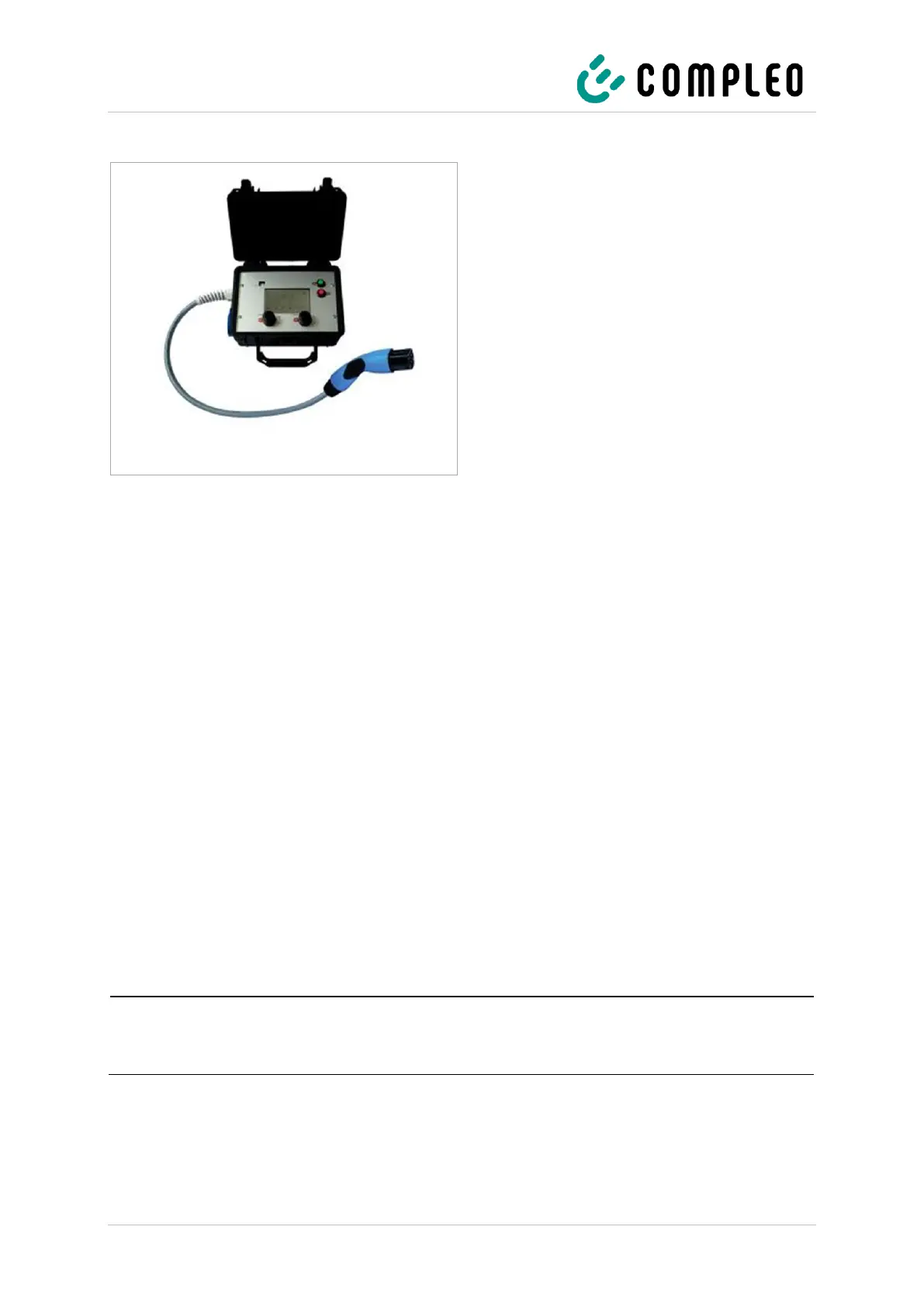
With the function simulator it is possible to
simulate the functions of an electric vehicle and
check the functionality of a charging system or
charging point.
The figure shows an example of a function
simulator for testing an AC charging system or AC
charging point.
Another suitable test device must be used for all
metrological tests.
6.2 System start-up
After the charging system has been correctly installed, the system can be started.
1. Switch on the main switch of the charging system.
2. Switch on the line and residual current circuit breaker.
The system starts up.
The duration of the system start-up may vary depending on the type of charging system, configuration
and product characteristics. The successful completion of the system start-up is indicated by the
status LEDs and the display according to the configuration and product scope of the charging system.
The average start-up time is approx. 60 seconds.
A successful system start-up is indicated by the LED of the respective charging point temporarily
lighting up green. In the case of a charging system with display, the message "Ready for operation" also
appears for the respective charging point.
In addition to the displays mentioned above, the current counter reading and the message "Ready for
operation" are shown on the display of any memory and display module (SAM) installed.
If explicitly requested by the customer, the backend connections can be configured and tested at
the factory. In this case, the backend connects directly to the associated charging system after
applying the operating voltage. This process may take a few minutes.