14 SAM_EN | 01 2022_05
2.8 Communication connections
The SAM is equipped with the following non-reactive communication interfaces:
• IR interface: Point-to-point connection to the electricity meter
• 20 mA interface: Point-to-point connection to the charging system control unit (LES)
• HMI interface (2 buttons and display) for interaction with the user
Connection to the electricity meter
The memory and display module is connected to the electricity meter via a secure connection. This connection
is established via an optical interface.
Depending on the operating state, the values are
• automatically sent out cyclically by the meter or
• - actively queried by the SAM.
Connection to the LES
The memory and display module is connected to the LES via a 20 mA interface (current loop). The SAM sends the
received meter values unchanged to the control unit. In addition, the result of a start and final meter reading
query is transmitted.
The control unit sends the following information to the SAM:
a) Start of the charging process for the corresponding delivery point
b) End of the corresponding charging process
c) ID for the associated start and final meter reading
d) Date and time
e) Voltage
f) Correction factor (resistance to system power loss)
2.9 Power supply
In the AC system, the AC meter is connected to the mains connection on the input side via electrical protective
measures such as charging station fuses and main switches. On the output side, the delivery point (AP) is supplied
with power via an AC contactor. The user can charge his vehicle via the delivery point (socket or charging cable).
For the DC system, the DC meter is connected on the input side via an AC/DC converter with integrated protective
devices. On the output side, the delivery point (AP) is supplied with power via DC contactors.
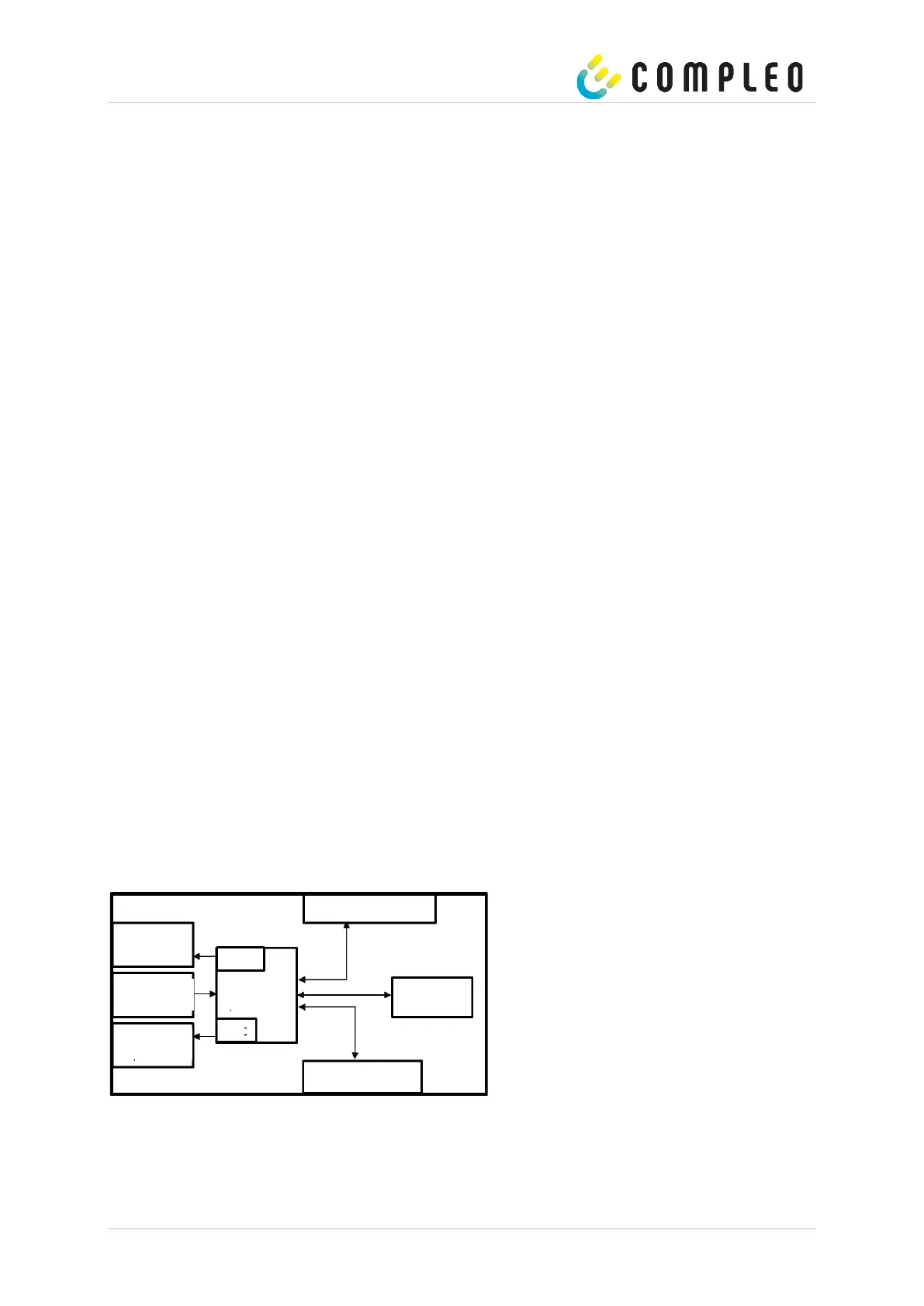
2.10 SAM module system overview
The following image shows the internal relevant components of the SAM.
Figure 6: Functional block diagram of the SAM
The memory and display module is equipped with the following components:
Micro-controller
The micro-controller has an integrated flash memory and an RTC.