18 SAM_EN | 01 2022_05
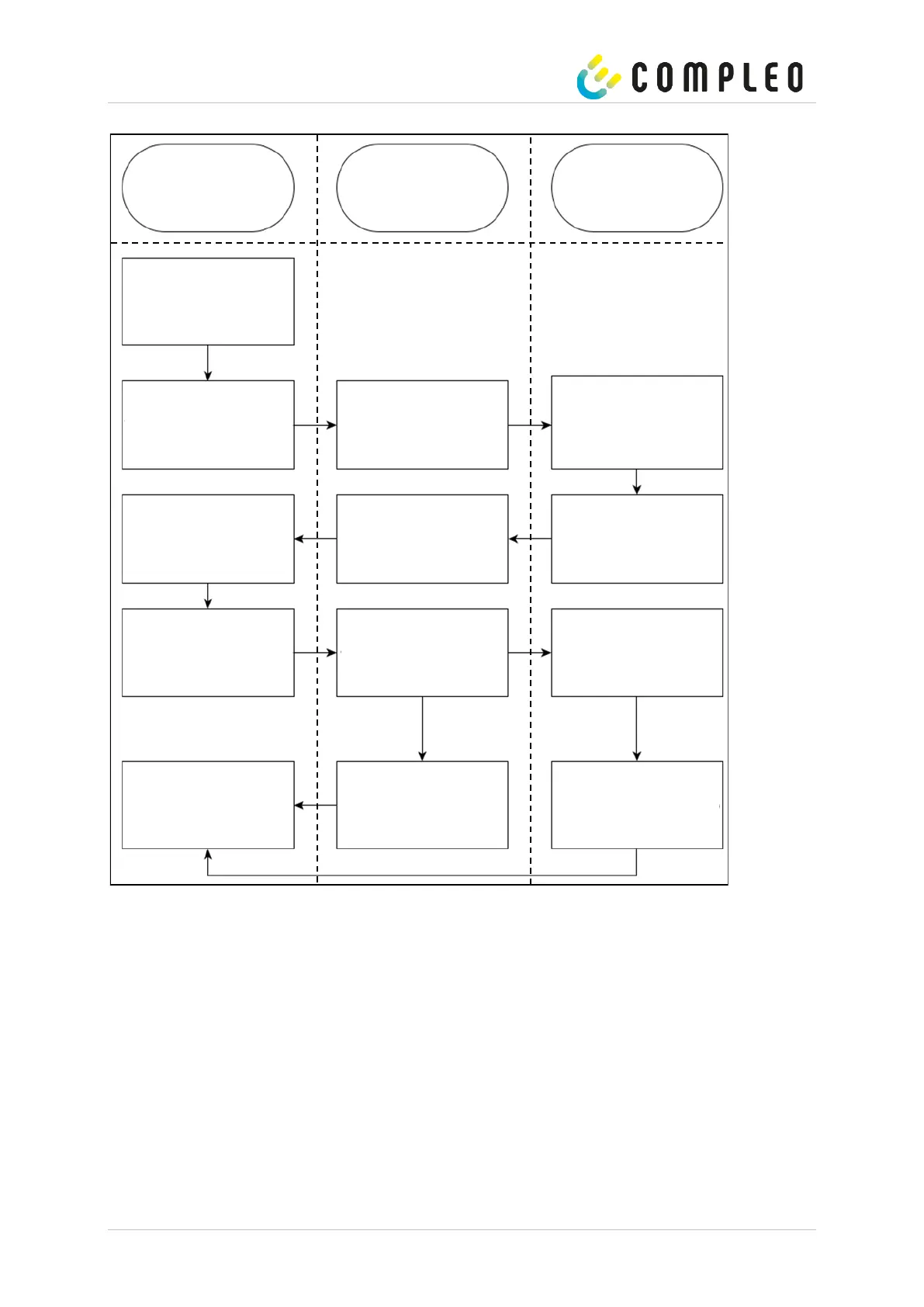
The following diagram illustrates the check procedure.
Figure 8: Test procedure regarding the stopwatch function in the manufacturing process.
Stopwatch (external
reference)
Start a simulated charging
process
Control unit (module B) or test
stand (moduleD) sends start
signal.
After receiving the start signal,
the PIN is toggled (flank) and
the internal stopwatch starts
running.
Start time measurement after
receiving the flank signal from
the PIN of the SAM.
Time measurement over period
X
Time measurement over period
X
Time measurement over period
X
Stop the simulated charging
process after period X.
Stop the simulated charging
process after period X.
After receiving the stop signal,
the PIN is toggled (flank) and
the internal stopwatch stops.
Stop time measurement after
receiving the flank signal from
the PIN of the SAM.
Evaluate and compare the
times measured by SAM and
stopwatch.
Response with the measured
time (ms, 3 digits) via 20 mA
interface.
Read the display or output the
measured time (ms, 3 digits) on
the test stand.