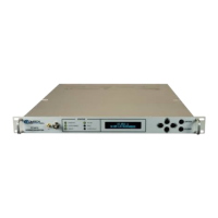
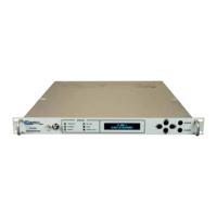
DT-4500 Series C- and Ku-Band Down Converters MN/DT4500.IOM
Introduction Revision 2
1–11
available on these legacy products.
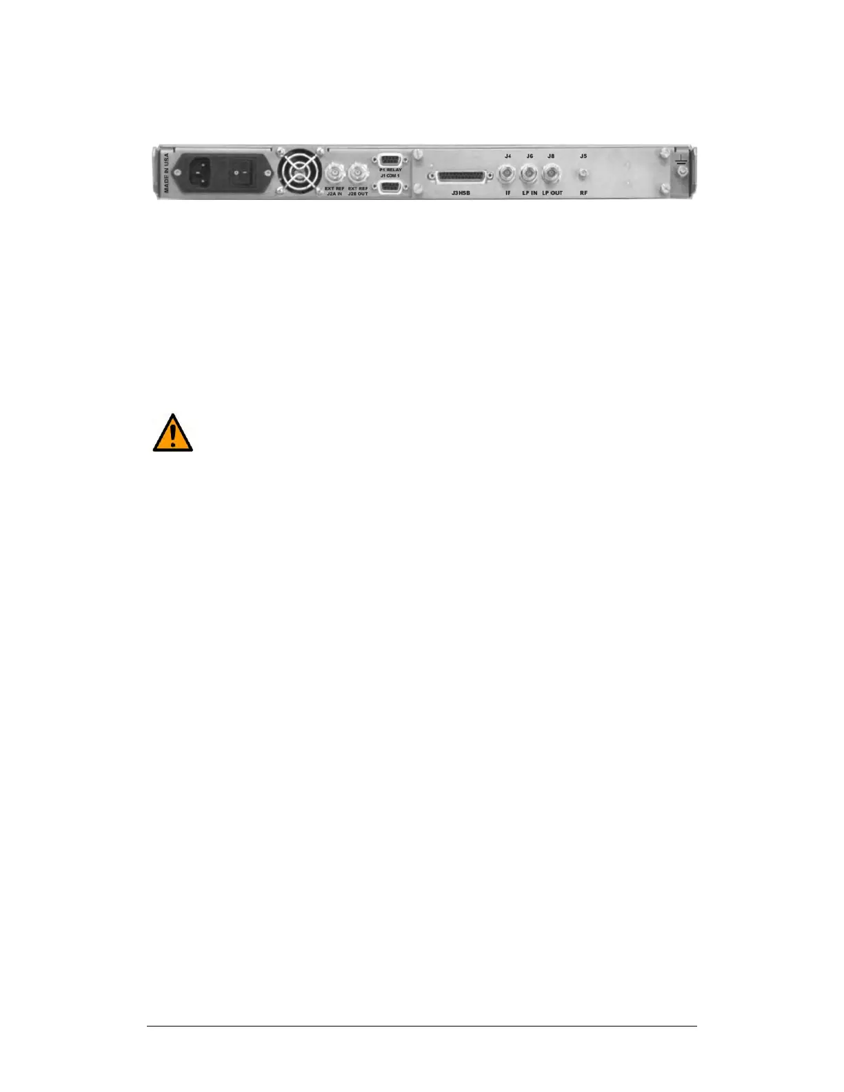
Figure 1-7. Rear Panel (with RSM) – Initially Released Chassis (OBSOLETE)
From left to right:
Item 1 – Power Connection (part of Power Supply module)
• The standard AC unit features a 90-250VAC Primary Input Power Supply
(IEC-60320 Type C14 three-prong male connector)
• The optional -48VDC unit features a terminal block power interface.
Item 2 – Unit Fusing (part of Power Supply module)
CAUTION
FOR CONTINUED OPERATOR SAFETY, ALWAYS REPLACE THE FUSES
WITH THE CORRECT TYPE AND RATING.
The unit uses two Slo-Blo fuses, one each for line and neutral fusing:
• The standard AC unit retains two T2.0A 5x20 mm fuses (250VAC time lag)
in a press-fit fuse holder.
• The optional DC unit retains two T3.15A 20 mm fuses in a press-fit fuse
holder.
Item 3 – Power Switch (part of Power Supply Module)
Use this switch to turn power to the unit on or off.
Item 4 – ‘J2A | REF IN’ Utility Connector
Use this BNC female connector to supply a 5/10 MHz master reference to the
entire chassis.
Item 5 – ‘J2B | REF OUT’ Utility Connector (OPTIONAL)
Use this optional BNC female connector to provide a 5/10 MHz external
reference for customer use.
Item 6 – ‘ETHERNET’ Ethernet Management Utility Port
Use this 100BaseTX Ethernet RJ-45 port for operation of the Ethernet remote
control interfaces.