15.1.1 Configuration
Before we start the script configuration, you should follow these steps:
1. Check the sensor and inputs signals settings – go to Diagnostics tab and while pushing the sen-
sor with hand observe the light indicators on the screen. The light should light up at the
moment of pushing the sensor and light should go out after releasing it. In case of any problems
go to 10.4 chapter (inputs signals). The sensor signal in the configuration window is called
“Probe”.
2. Make reference move of all axes.
3. On the main screen switch the coordinates display mode for machine display (absolute) – icon
.
4. Secure the tool in the spindle holder (for the firsts test – the cheapest is the best).
5. In manual feed mode move to the center of the sensor measuring surface. Note XY coordinates.
6. In stepper mode slowly lower the Z axis until the signal from the sensor appears and note the Z
coordinate.
7. Go with Z-axis up to the level you consider as safe. A small explanation here - as written above,
while measurement there is rapid slide down to some level by G0 command first. You have to
assess to what Z-axis level it can slide down quickly. It depends on maximum length of tools that
will be measured. You can also enter "0" as a safe Z and then measurement starts from the top
position.
8. Move the XY
axes to place yourself somewhere above the worktable.
9. Using the stepper mode, slowly slide the tool down to the worktable surface and note the Z coor-
dinate.
10. Turn off the absolute coordinates mode by clicking icon.
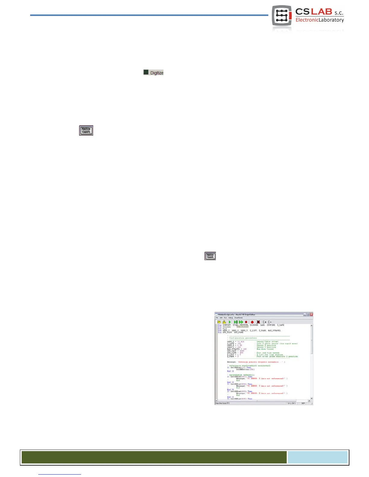
When you have noted all necessary data, open the downloaded toollenght.m1s file in any text editor (e.g.
notepad). Then select all using mouse or by pressing "CTRL + A" and copy to clipboard - "CTRL + C".
In Mach standard graphical interface, on the main screen there is an "Auto Tool Zero" button. This button
is defined by default as calling a macro, so there is no need to add a new button in the graphical editor.
To connect the mentioned above button to our macro, select in
the menu: "The operator / Edit Button Script". The "Auto Tool
Zero" button and several others should start to
blink. Click on it
and open Mach3 text editor.
Sometimes there is a single text line, if so - you must delete it,
and then press CTRL + V to paste our macro.
Now just enter a few parameters based on the coordinates,
which we noted earlier. All configuration data can be found
under "Configuration parameters" line.
CS- Lab s.c. – CSMIO/IP- A - CNC controller
Page 105
 Loading...