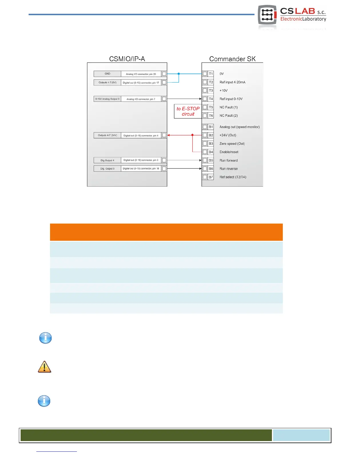
4.13.4 Inverter connection using analog output.
In the example above you can see connection of Commander SK for spindle support.
CSMIO/IP-A outputs in use:
AGND – reference potential for analog
Voltage input 0-10V of speed com-
mand
CSMIO/IP digital outputs Power
DB25 – Digital outputs (0-15)
DB25 – Digital outputs (0-15)
24V output for controlling signals
DB25 – Digital outputs (0-15)
DB25 – Digital outputs (0-15)
Note that every group of CSMIO/IP-A digital outputs can work on a different potential. In this case we used
24V output of the inverter.
Do no forget to set the configuration parameters of the inverter properly. Incorrect settings may cause - in
the best case - the inverter error, in the worst - the spindle motor becomes permanently damaged (such
damage is not covered by warranty).
Mach3 program configuration, concerning use of a spindle with revs control was described in chapter 10 -
"Mach3 Configuration".
CS- Lab s.c. – CSMIO/IP- A - CNC controller
Page 38