EasyManua.ls Logo

CS-Lab CSMIO/IP-A

CS-Lab CSMIO/IP-A
111 pages
To Next Page IconTo Next Page
To Previous Page IconTo Previous Page
Loading...
In the CSMIO/IP controller, there was additionally implemented fault signals support from servo drives.
Details in the „Additional configuration functions” chapter.
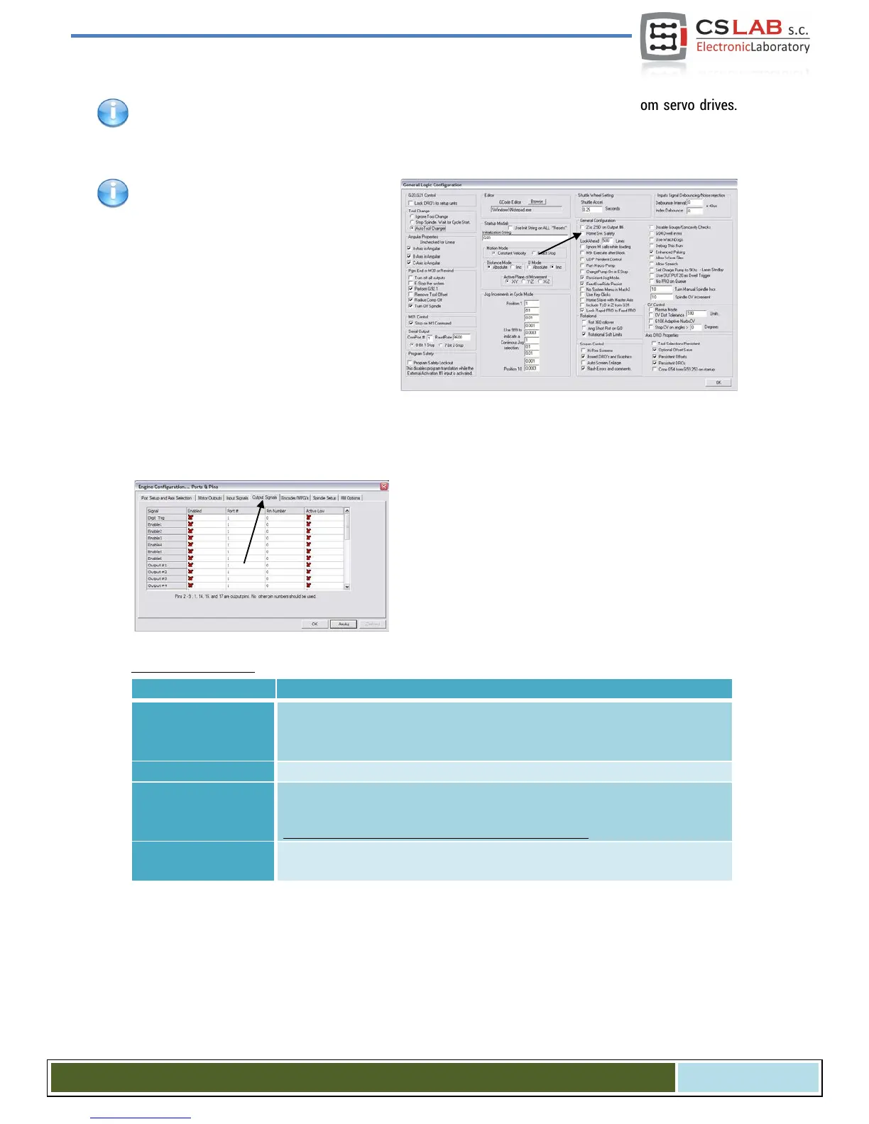
Since the CSMIO/IP v1.07 software version
there is a possibility to give the same input
PIN as LIMIT and HOME. You should disable
the „Home Sw. Safety” option in „General
Config” window of Mach3 program. With
„Home Sw. Safety” option disabled, the LIM-
IT signals are not monitored during homing.
10.5 Configuration of digital output signals
Digital outputs are used for such tasks as e.g. spin-
dle/torch activation, activation/releasing brakes of elec-
tromagnetic motors, cooling, solenoids valves activation,
etc.
The outputs configuration is almost the same as the
inputs configuration.
Columns explanation:
Name of the column
Description
Enabled
Green tick means we are using the signal.
Red X cross means that we are not interested in that signal and it
should not be used
Port #
Input port number for CSMIO/IP-A it is always port no. 10.
Pin Number
Pin number, means CSMIO/IP-A output number, e.g. output no. 5 of the con-
troller we put here as pin no. 5.
It doesn’t mean a pin number on CSMIO/IP connector.
Active Low
Signal polarization change, it is a selection whether the signal should be ac-
tive at 0V or at 24V.
CS- Lab s.c. CSMIO/IP- A - CNC controller
Page 60

Table of Contents

Other manuals for CS-Lab CSMIO/IP-A

Related product manuals