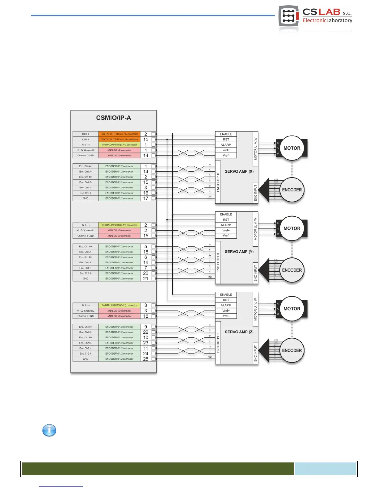
4.13.2 Servo drives connection
Below you can see sample servo drive connection. We can differentiate three basic signals functions: en-
coder, analog signal +/-10V and digital control signals.
Encoder signals inform the controller about current motor (axis) position. Analog +/-10V signal controls
motor rpm via servo amplifier and control signals are: drive activation, fault reset and a signal that informs
about alarm (e.g. overload, overheat etc.) of the drive.
Servo amplifiers form different manufacturers may differ a bit but the main rule is practically the same.
Signals names are changed, sometimes I/Os work as PNP and sometimes as NPN, but almost always ser-
vo amplifier connection looks like shown above.
Encoder signals and analog +/- 10V signal always connect using Twisted-Pair cable.
CS- Lab s.c. – CSMIO/IP- A - CNC controller
Page 36