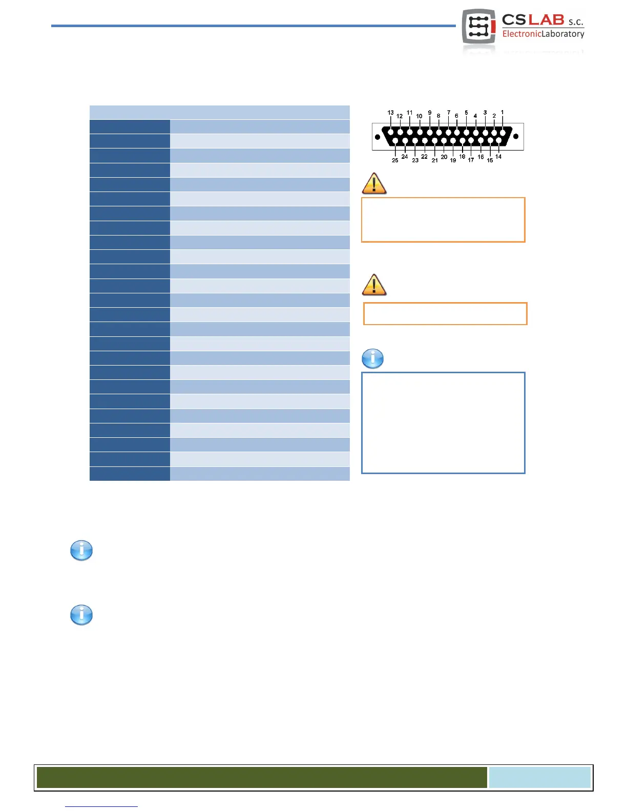
4.3 Encoder inputs connector (0 / 1 / 2)
Oz
Axes by default are assigned to the following channels: XCh0 / YCh1 / ZCh2 … CCh5. It can be
changed in plugin configuration.
While "A, B" signals signage is quite standard, the "I" index signal is signed by encoder manufacturers in
different ways: "Z, C, … etc."
Pay attention to not exceed the per-
missible voltage (5VDC) on the input
lines.
The encoder inputs of CSMIO/IP-A
require differential signal. If connect-
ed encoder has a common output
then you should use special convert-
er. Connection of A-, B-, I- to GND
causes axis position will be distorted.
Max. PINs load is +5Vto 200mA / pin.
CS- Lab s.c. – CSMIO/IP- A - CNC controller
Page 18