INDEX
1. General ......................................................................................................................................... 6
1.1 Signs used in this guide .................................................................................................................. 6
1.2 Content .......................................................................................................................................... 7
1.3 Standards compliance .................................................................................................................... 8
1.4 Specification .................................................................................................................................. 8
2. Safety ........................................................................................................................................... 9
2.1 Example of direct E-Stop signal connection .................................................................................. 10
2.2 Example of E-Stop Signal connection using PILZ module .............................................................. 11
3. Recommendations for mechanical installation ................................................................................ 12
3.1 Examples of components arrangement in a control cabinet. ......................................................... 12
3.1.1 Block scheme pictorial view .............................................................................................. 12
3.1.2 Control cabinet made by CS-Lab Company ......................................................................... 13
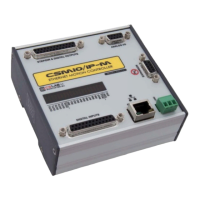
4. Connectors, controls and electrical installation of the device ............................................................ 14
4.1 Connectors arrangement on the device ......................................................................................... 14
4.2 Analog inputs/outputs connector.................................................................................................. 15
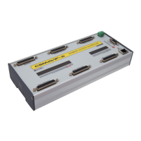
4.2.1 Signals on a Terminal Block connector .............................................................................. 16
4.2.2 Example – connection and configuration of FRO and SRO potentiometers ........................... 17
4.3 Encoder inputs connector (0 / 1 / 2) .............................................................................................. 18
4.3.1 Signals on a Terminal Block connector .............................................................................. 19
4.3.2
Example - connection of an encoder to Ch0 channel ........................................................... 19
4.4 Encoder inputs connector (3 / 4 / 5) .............................................................................................. 21
4.4.1 Signals on a terminal block connector ............................................................................... 21
4.5 Digital inputs connector (0-11) ..................................................................................................... 22
4.5.1 Input circuits construction ................................................................................................ 23
4.5.2 Signals on a terminal block connector ............................................................................... 23
4.5.3 Examples - input signals connection .................................................................................. 24
4.6 Digital inputs connector (12-23) ................................................................................................... 26
4.6.1 Signals on a terminal block connector ............................................................................... 26
4.7 Digital outputs connector (0-15) ................................................................................................... 27
4.7.1 Output circuits construction .............................................................................................. 28
4.7.2 Signals on a terminal block connector ............................................................................... 28
4.7.3 Example – spindle activation signal ................................................................................... 29
4.8 Expansion modules connector ...................................................................................................... 30
4.9 Power connector .......................................................................................................................... 31
4.10 Communication connector – Ethernet .......................................................................................... 31
CS- Lab s.c. – CSMIO/IP- A - CNC controller
Page 2