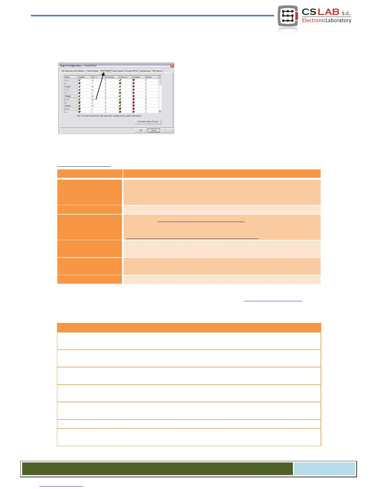
10.4 Configuration of digital input signals
Configuration of the input signals we call from menu
„ConfigPorts and Pins”, by selecting „Input Signals”
tab. A list of standard input signals will appear and you
can assign these signals to hardware inputs of
CSMIO/IP-A controller.
Columns explanation:
• Green tick means we are using the signal.
Red X cross means that we are not interested in that signal and it
should not be used
Input port number – for CSMIO/IP it is always port no. 10.
Pin number, means the CSMIO/IP input number, e.g. input no. 14 of the con-
troller we put here as a pin no. 14.
It doesn’t mean a pin number on CSMIO/IP connector.
Signal polarization change, it is a selection whether the signal should be ac-
Signal emulation with keyboard shortcut. In CSMIO/IP-A controller, only some
signals may be emulated: „THC On”, „THC Up”, „THC Dn” and „Probe”.
Keyboard shortcut for signal emulation.
Detailed description of the signals is available in ArtSoft® documentation:
www.machsupport.com, below
we present short description of the most important.
X++, Y++, Z++, A++, B++, C++
Hardware signals of positive limits. A machine stops immediately
when one of the signals becomes active.
X--, Y--, Z--, A--, B--, C--
Hardware signals of negative limits. A machine stops immediately
when one of the signals becomes active.
X Home, Y Home, Z Home,
A Home, B Home, C Home
Input signals for general use. They can be used e.g. in VisualBasic®
scripts.
Signals of a measurement probe, e.g. sensor of tool length measure-
ment sensor.
Index from a spindle for rotational/threading speed measurement.
Motion forcing, if one of LIMIT signals is active. It is useful to allow for
move back off the limit switch. If we are using Auto Limit Override
CS- Lab s.c. – CSMIO/IP- A - CNC controller
Page 58