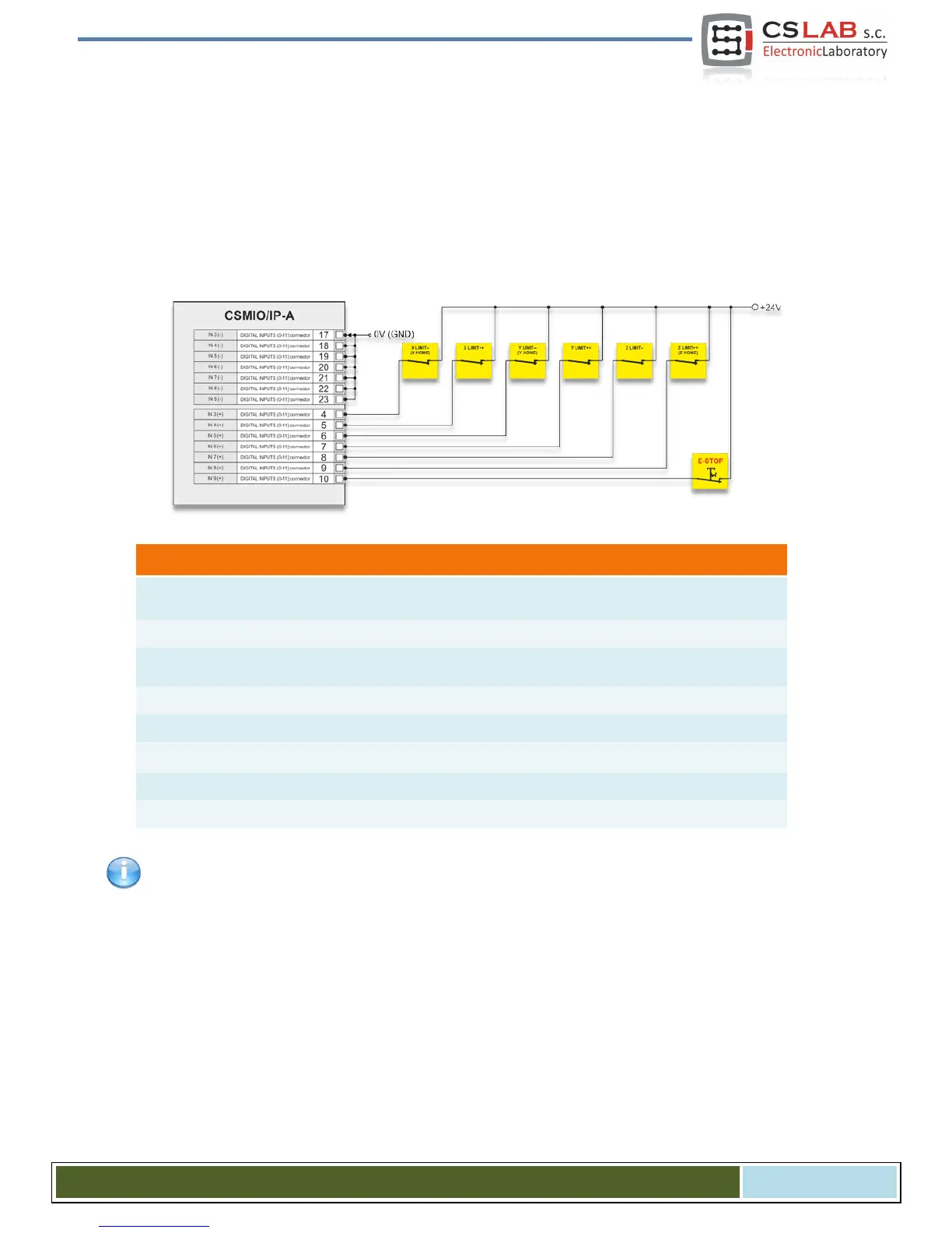
4.13.3 Limit switches and E-STOP signal.
The easiest option ensuring a necessary safety is to use two (2) switches, both sides of an axis. In this
case one switch works only as safety LIMIT signal and the other has double function: LIMIT and HOMING.
In our example of three axis plotter, we are homing the X and Y axes on the negative side (towards de-
creasing coordinates), so the double function will be performed by LIMIT-- switches. And we are homing Z
axis upward and up move usually, on CNC machines is a movement in the positive direction. So for Z axis
the double function will be performed by LIMIT++ switch.
Optical inputs in CSMIO/IP-A require both ‘+’ and ‘-‘ potentials connection. The ‘-‘ Pins of digital inputs
used are connected to 0V potential - see "Power supply" section.
CS- Lab s.c. – CSMIO/IP- A - CNC controller
Page 37