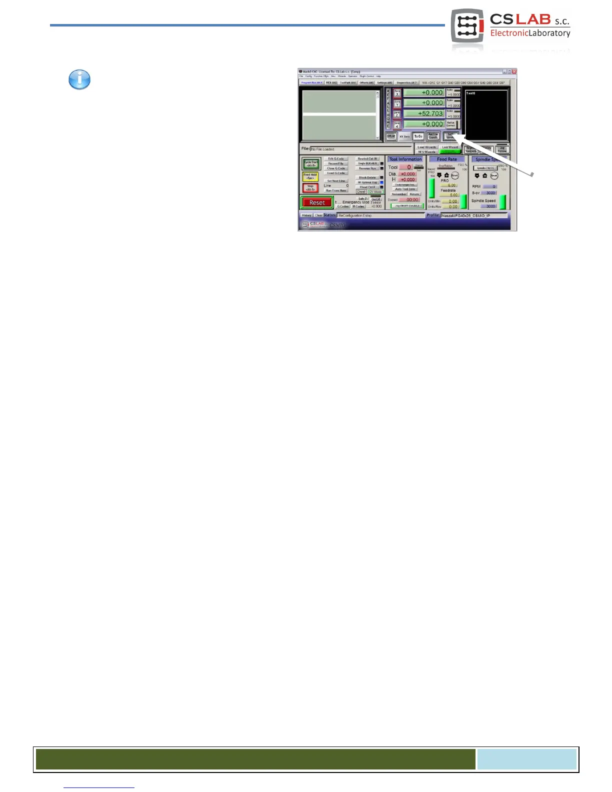
Home
CS-Lab
Controller
CSMIO/IP-A
CS-Lab CSMIO/IP-A User Manual
4
of 1
of 1 rating
111 pages
Give review
Manual
Specs
To Next Page
To Next Page
To Previous Page
To Previous Page
Loading...
When
softwar
e li
mits opt
ion is act
iv
e („S
oft
Limit”
on a Mac
h3 main scre
en), the CSMI
O/IP
-A
controll
er does n
ot let f
or a
ny move if a
xes
of a
machine
are not hom
ed.
Current s
tatus
of the f
unct
ion is sho
wn by a
green li
ght around „S
oft Limit
” button
.
CS
-
Lab s.c.
–
CSM
IO
/IP
-
A
-
CNC controller
Page
66
65
67
Table of Contents
Default Chapter
2
Table of Contents
2
1 General
6
Signs Used in this Guide
6
Content
7
Standards Compliance
8
Specification
8
2 Safety
9
Example of Direct E-Stop Signal Connection
10
Example of E-Stop Signal Connection Using PILZ Module
11
3 Recommendations for Mechanical Installation
12
Examples of Components Arrangement in a Control Cabinet
12
Block Scheme Pictorial View
12
Control Cabinet Made by CS-Lab Company
13
4 Connectors, Controls and Electrical Installation of the Device
14
Connectors Arrangement on the Device
14
Analog Inputs/Outputs Connector
15
Signals on a Terminal Block Connector
16
Example - Connection and Configuration of FRO and SRO Potentiometers
17
Encoder Inputs Connector (0 / 1 / 2)
18
Signals on a Terminal Block Connector
19
Example - Connection of an Encoder to Ch0 Channel
19
Encoder Inputs Connector (3 / 4 / 5)
21
Signals on a Terminal Block Connector
21
Digital Inputs Connector (0-11)
22
Input Circuits Construction
23
Signals on a Terminal Block Connector
23
Examples - Input Signals Connection
24
Digital Inputs Connector (12-23)
26
Signals on a Terminal Block Connector
26
Digital Outputs Connector (0-15)
27
Output Circuits Construction
28
Signals on a Terminal Block Connector
28
Example - Spindle Activation Signal
29
Expansion Modules Connector
30
Power Connector
31
Communication Connector - Ethernet
31
Recommended Cables
32
LED Lights Meaning
33
Types and Location of the Leds
33
Leds State Description - Statx
34
Example - a Scheme View of a 3-Axis Plotter (XYZ)
35
Power Supply
35
Servo Drives Connection
36
Limit Switches and E-STOP Signal
37
Inverter Connection Using Analog Output
38
Automatic Control of Drives Power Supply (HV)
39
5 Recommendations and Drives Selection (Motors Drives)
40
6 Precise Homing with Encoder INDEX Signal
41
Homing on "Index" Enable
41
7 LAN Connection and Configuration
42
Direct Connection to the PC
42
Windows ® XP Configuration
42
Windows ® 7 Configuration
43
Local Network with Router and DHCP
46
8 Mach3 Program - General Information
47
Recommended PC Configuration
49
9 Software Installation
50
Mach3 Installation
50
Microsoft ® .Net Installation (Older Operating Systems)
51
Installation of CSMIO/IP Firmware
51
Administrator Rights in Windows® Vista and Windows® 7
53
10 Mach3 Program Configuration
54
Configuration Profile Creation
54
The First Run
55
Configuration of Axes Used in a Machine
57
Configuration of Digital Input Signals
58
Configuration of Digital Output Signals
60
Configuration of Spindle and Cooling
62
Analog Output Configuration
62
Problematic PWM Control Function
63
Configuration of Resolution, Speed and Acceleration
64
Configuration of Directions, Homing and Software Limits
65
Configuration Functions in a Plug-In Window
67
Axes Special Functions
67
Spindle Configuration
70
Override Sources - Feed Speed and Spindle Revs Corrections Source Selection
71
Plasma - Additional Functions for Plasma Cutters
72
Misc IO - Special Functions Related to I/O
72
Other - Other Plugin Functions
73
Selection of Inch/MM Units
75
Some Parameters in the General Config Window
75
11 PID Controller (Regulator)
77
What Is PID Controller
77
PID Controller Terms (Parameters) Operation
78
The Proportional Term - P
78
The Integral Term - I
78
The Derivative Term - D
79
The „Sixth" Sense - the Mysterious K
79
VFF Parameter
79
The Actual Controller in CSMIO/IP-A
80
The Order of Controllers Tuning
80
PID Regulator Tuning" Window
81
Manual PID Regulator Tuning Procedure in CSMIO/IP-A
83
PID Tuning - Practical Tips
85
Slave Axis
85
An Axis with Toothed Racks (Straight Toothed)
85
Laud Noises at Standstill
86
Cannot Start Tuning Because an Axis Does Not Move
86
An Axis after Activation Jerks or Starts to Move with Max. Speed
86
Cannot Tune an Axis
86
Autotuning - Automatic PID Tuning
87
12 First Tests
89
Checking the Input Signals
89
Verification of Axes Scaling and Motion Directions
90
HOMING and Software Limit Switches Test
91
First Homing
91
Softlimit Switches
91
Test of Spindle and Cooling
92
13 Sample Treatment Step by Step
93
Project and G-Code Files Preparing
93
Preparing Machine and Mach3 Program
97
We Begin the Treatment
99
14 A few Practical Notes about Mach3 Program and CSMIO/IP-A
101
15 Visualbasic ® Macros
104
Automatic Tool-Length Measurement
104
Configuration
105
Automatic Tool Change Macro
106
Addition a - Slave Axis Configuration Example
107
Defining Axes Used in Mach3 Program
107
Axis Scaling and Configuration
107
Activation and Choice of Slave Axis
107
LIMIT and HOMING Switches
108
Axis Direction Settings
108
Manual Feed Test
108
Automatic Reading of HOME Switches Position Difference
108
Geometry Correction Mode Activation
109
Addition B - -CSMIO/IP-A Firmware Update
110
How to Check Your Current Firmware Version
110
Update Application (Uploader)
110
Plugin File Update
111
Update Verification
111
Other manuals for CS-Lab CSMIO/IP-A
Tuning Guide
20 pages
4
Based on 1 rating
Ask a question
Give review
Questions and Answers:
Need help?
Do you have a question about the CS-Lab CSMIO/IP-A and is the answer not in the manual?
Ask a question
CS-Lab CSMIO/IP-A Specifications
General
Brand
CS-Lab
Model
CSMIO/IP-A
Category
Controller
Language
English
Related product manuals
CS-Lab CSMIO/IP-M
69 pages