EasyManua.ls Logo

Curtis 1226 - User Manual

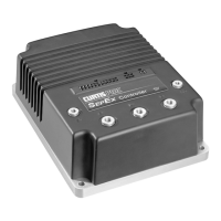
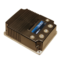
Curtis 1226
99 pages
Print Icon
To Next Page IconTo Next Page
Loading...
Read Instructions Carefully!
Specications are subject to change without notice.
© 2019 Curtis Instruments, Inc. ® Curtis is a registered trademark of Curtis Instruments, Inc.
© The design and appearance of the products depicted herein are the copyright of Curtis Instruments, Inc. 53229, RevA 9/19
Curtis Instruments, Inc.
200 Kisco Avenue
Mt. Kisco, NY 10549
www.curtisinstruments.com
Manual
Model 1226
Brushed Permanent Magnet Controller

Table of Contents

Questions and Answers

  • J
    Jeffrey NewtonSep 1, 2025
    What to do if Curtis 1226 Controller displays NV memory failure?
    • M
      Melissa FrazierSep 1, 2025
      If the Curtis Controller displays an 'NV Memory Failure', it means there's a failure to read or write to nonvolatile (NV) memory, or there's an internal controller fault. Download the correct firmware and default parameter settings, then cycle the keyswitch.
  • C
    chungsaraSep 12, 2025
    What does Curtis 1226 parameter out of range mean?
    • E
      eddie65Sep 12, 2025
      If the Curtis Controller displays 'Parameter Out Of Range', it means a parameter is set to an invalid value. Update the parameter to a valid value.
  • J
    Jesse MckayAug 30, 2025
    What does it mean if Curtis 1226 shows main contactor welded and what to do?
    • H
      Hannah BrandtAug 31, 2025
      If the Curtis Controller indicates that the main contactor is welded, it means the main contactor tips are welded closed, motor phase M1 or M2 is disconnected or open, or an alternate voltage path is providing current to the capacitor bank. Address the possible causes, then cycle the keyswitch.
  • C
    Christopher GrossSep 14, 2025
    What does Curtis Controller EMR Switch Redundancy mean?
    • T
      Tabitha WatsonSep 15, 2025
      If the Curtis Controller displays 'EMR Switch Redundancy', it means either or both Emergency Reverse input switches are inoperative, resulting in an invalid state, or there is dirt or moisture in the switches. Address the possible causes, then cycle the keyswitch.
  • J
    Jamie DavisSep 14, 2025
    What does Curtis 1226 emer rev hpd mean?
    • B
      Bobby VasquezSep 14, 2025
      If the Curtis Controller displays 'Emer Rev HPD', it means the throttle, direction, and interlock inputs were not returned to neutral after an emergency reverse operation. If the EMR Dir Interlock parameter’s value is On, clear the interlock, throttle, and direction inputs. Otherwise, clear the throttle and direction inputs.
  • E
    emily10Sep 18, 2025
    What does Curtis Controller AUX 1 Driver Shutdown mean?
    • C
      Christina DaySep 18, 2025
      If the Curtis Controller displays 'AUX 1 Driver Shutdown', it means the driver is open or shorted, the controller’s or contactor coil’s connector pins are dirty, or there are bad connector crimps or faulty wiring. Repair the wiring and connections, then cycle the keyswitch.
  • J
    jamesfosterSep 23, 2025
    What does Curtis Controller Driver 1 Shutdown mean?
    • R
      robinkhanSep 23, 2025
      If the Curtis Controller displays 'Driver 1 Shutdown', it could indicate that the coil is open or shorted, the connector pins for the controller or contactor coil are dirty, there are bad connector crimps or faulty wiring, or there is driver overcurrent. Address the possible causes, then cycle the keyswitch.
  • J
    Jonathan CareyAug 27, 2025
    What causes severe B+ undervoltage in a Curtis 1226 and how to fix it?
    • B
      Brian StoneAug 27, 2025
      A severe B+ undervoltage in your Curtis Controller can be caused by several factors: a system other than the controller draining the battery, high battery resistance, a disconnected battery, a blown B+ fuse, the main contactor failing to close, or incorrectly configured undervoltage parameters. Address these possible causes and then cycle the keyswitch.
  • J
    justinperezAug 26, 2025
    What does Curtis 1226 Controller BB Wiring Fault mean?
    • L
      Leah RodriguezAug 26, 2025
      A 'BB Wiring Fault' on the Curtis Controller indicates bad crimps or faulty wiring for the emergency reverse normally open switch. Fix the wiring, then cycle the keyswitch.
  • A
    Anna CunninghamAug 25, 2025
    What to do if Curtis 1226 displays severe overtemp?
    • N
      Natalie PowellAug 26, 2025
      If your Curtis Controller is showing a severe overtemp error, it means the controller is operating in an extremely hot environment. Decrease the heatsink temperature to below 85°C, then cycle the keyswitch.

Summary

1 - OVERVIEW

2 - INSTALLATION AND WIRING

HIGH CURRENT CONNECTIONS

Details on M5 bolt-on terminals for battery and motor connections.

LOW CURRENT CONNECTIONS

Information on the 3 low-current connectors (J1, J2, J3).

WIRING DIAGRAM: STANDARD CONFIGURATION

Representative wiring diagram for typical Class III vehicle applications.

INPUTS AND OUTPUTS (I;Os)

Overview of flexible I/Os and predefined functions for applications.

Driver Outputs

Information on the 3 generic drivers supporting PWM and different modes.

Throttle Pot

How analog inputs support throttle potentiometer circuits.

3 - PROGRAMMABLE PARAMETERS

APPLICATION SETUP MENU

Contains menus for configuring application-specific settings.

Speed Mode Menu

Parameters to configure speed-related functions like max/min speeds.

Mode 1 and Mode 2 Menus

Parameters to configure two distinct speed modes for different conditions.

Fine Tuning Menu

Defines high and low speed thresholds for various parameters.

Throttle Menu

Specifies throttle type, responsiveness, and HPD/SRO function.

Understanding the Throttle Response Parameters

Explains deadband, max, offset, and map parameters affecting throttle response.

Understanding the HPD;SRO Function

Explains High Pedal Disable and Static Return to Off safety functions.

Battery Menu

Menus for battery voltage monitoring and protection settings.

BDI Setup Menu

Parameters for configuring the Battery Discharge Indicator (BDI) output.

Emergency Reverse Menu

Configuration options for the emergency reverse feature.

EMERGENCY REVERSE MENU

Detailed configuration for the emergency reverse safety function.

Controller Setup Menu

Contains menus for configuring inputs, outputs, and limits.

Analog Inputs Menu

Menus for configuring analog inputs 1 through 5.

IO Assignment Menu

Assigns functions to switches and controls for analog inputs.

Current Limits Menu

Sets maximum current limits for drive, boost, regen, and brake operations.

Motor Setup Menu

Configuration for motor resistance, current rating, and speed settings.

4 - MONITOR MENU

5 - INITIAL SETUP

Step 1. Prepare the Vehicle

Steps for preparing the vehicle before controller programming.

Step 2. Configure the Throttle

Procedures to set up the throttle type and ensure full range operation.

Configure the Deadband

Tuning the throttle's deadband for proper neutral range and brake engagement.

Configure the Wiper Voltage

Setting wiper voltage to achieve 100% controller output at full throttle.

Confirm Throttle Operation

Verifying correct throttle operation and polarity for reverse features.

Step 3: Verify the Vehicles Configuration

Checking critical parameters and switch states for correct configuration.

Step 4: Set the System Resistance

Procedure to accurately set the System Resistance parameter for performance.

6 - TUNING VEHICLE PERFORMANCE

Step 1: Set the Maximum and Minimum Speeds

Setting speed limit pot maximum and minimum positions for each speed mode.

Step 2: Set the Acceleration and Deceleration Rates

Configuring acceleration and deceleration rates for smooth throttle response.

Step 4: Adjust IR Compensation

Configuring IR Comp and Anti-Rollback Comp for load and slope conditions.

Step 5: Fine-tune the Vehicles Response Smoothness

Adjusting Gear Soften and Soft Start for smoother vehicle response.

7 - CALIBRATING THE BATTERY DISCHARGE INDICATOR (BDI) OUTPUT

Step 8: Test and Tune

Testing and fine-tuning the BDI configuration for accuracy.

8 - DIAGNOSTIC AND TROUBLESHOOTING

PROGRAMMING DEVICE DIAGNOSTICS

Using programming devices to view real-time data and faults.

Fault Codes

Explains fault code structure and how LEDs indicate digits.

Troubleshooting Faults

Guidance on interpreting faults and their causes and actions.

APPENDIX C - CURTIS PROGRAMMING DEVICES

Curtis 1226 Specifications

General IconGeneral
BrandCurtis
Model1226
CategoryController
LanguageEnglish

Related product manuals