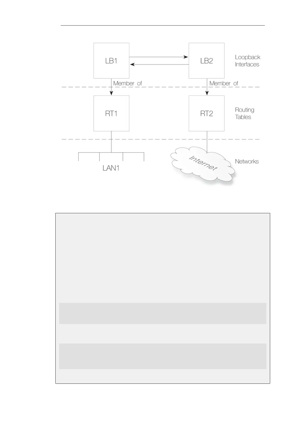
Figure 3.10. Components of Loopback Interface Setup
Example 3.25. Creating a Loopback Interface Pair
This example shows how to create a loopback interface pair called LB1 belonging to the RT1
routing table and LB2 belonging to the RT2 routing table.
LB1 will have the IPv4 address 127.0.6.1 and network 127.0.6.0/24. LB2 will have the IPv4 address
127.0.5.1/24 and network 127.0.5.0/24.
Traffic routed by the RT1 table into the LB1 interface will now exit on the LB2 interface and be
then routed using the RT2 routing table.
Command-Line Interface
A. Create the first loopback interface:
gw-world:/> add Interface LoopbackInterface LB1
IP=127.0.5.1
Network=127.0.5.0/24
MemberOfRoutingTable=RT1
B. Create the second loopback interface:
gw-world:/> add Interface LoopbackInterface LB2
IP=127.0.6.1
Network=127.0.6.0/24
LoopTo=LB1
MemberOfRoutingTable=RT2
Chapter 3: Fundamentals
217