Design Guide | iC2-Micro Frequency Converters iC2-Micro Frequency Converters
NOTICE
l RS485 termination switch should be set to ON if the drive is at the end of the fieldbus.
l Do not operate RS485 termination switch when the drive is powered on.
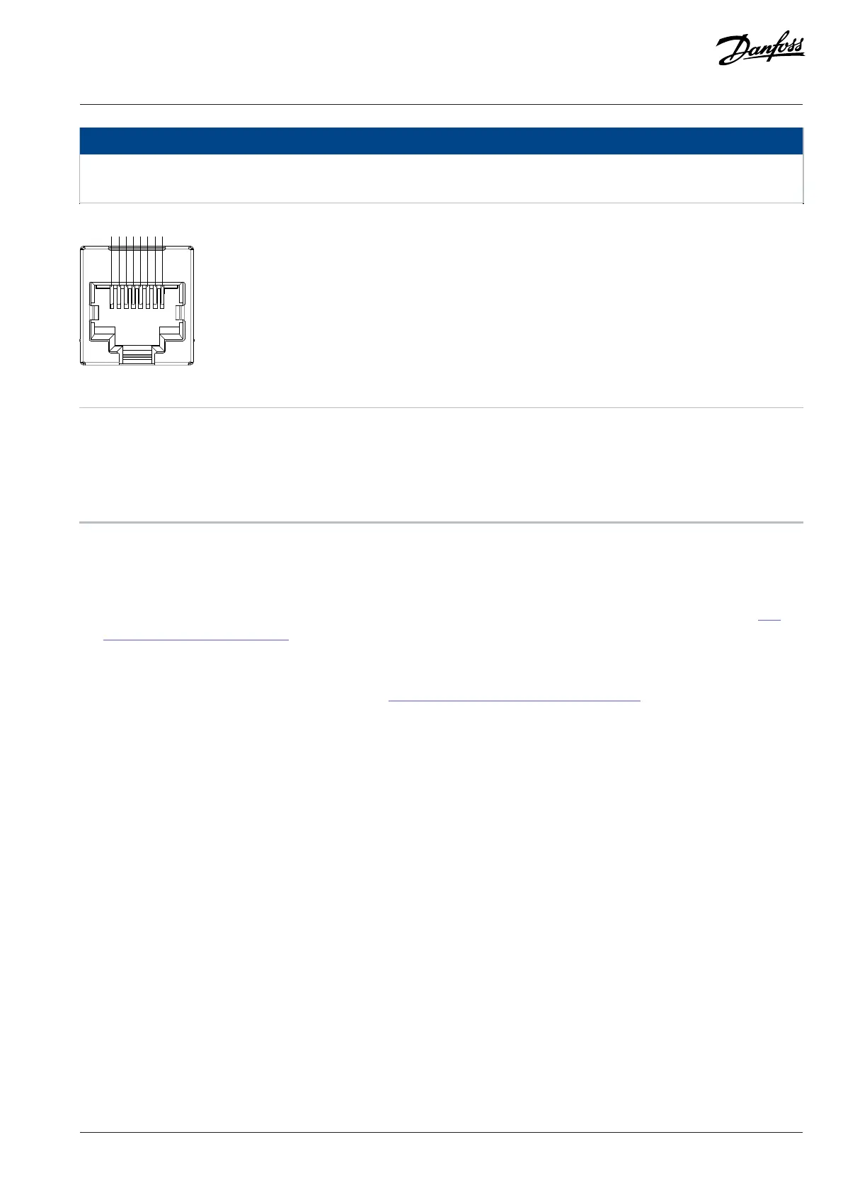
Figure 7: Pin Definition of RJ45
1 5V power supply 2 5V power supply
3 GND 4 RS485_P
5 RS485_N 6 GND
7 Reserved 8 Reserved
3.5.3 Control Panel and Control Panel 2.0 OP2
The drive has 2 types of control panels as follows:
l Control Panel: It is inbuilt and by default delivered with the drive. The Control Panel buttons and indicators are described in 3.5.4
Control Panel Buttons and Indicators.
l Control Panel 2.0 OP2: An optional (accessory) control panel which provides better user experience. This type of control panel
enables easy setup of the drive via parameters, monitoring of the drive status, and visualization of event notifications. The Control
Panel 2.0 OP2 buttons and indicators are described in 3.5.5 Control Panel 2.0 OP2 Buttons and Indicators.
A more detailed overview of Control Panel 2.0 OP2 is as follows:
l 2.03” monochromatic user interface.
l Visual LEDs to identify drive status.
l Control of the drive and easy switch between local and remote operations.
l Multilingual display which shows parameters, selections, and status more clearly.
l Parameter display supports alphanumeric, special characters, integers, floating points, choice lists, and commands to configure
application data.
l Parameter settings of the drive can be copied to other drives for easy commissioning.
l Installation on a cabinet door using a mounting kit option.
Danfoss A/S © 2024.08 AJ402315027937en-000401 / 130R1239 | 21