Table 49: Recommended Screws and Bolts
Protection rating Enclosure size Recommended screw/bolt Maximum torque [Nm (in-lb)]
MA01c M4 1.5 (13.3)
MA02c M4 1.5 (13.3)
MA01a M4 1.5 (13.3)
MA02a M4 1.5 (13.3)
MA03a M5 1.5 (13.3)
MA04a M6 1.5 (13.3)
IP20/Open Type
MA05a M6 1.5 (13.3)
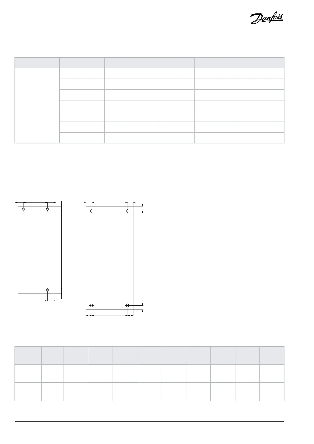
6.7.5 Drilling Patterns
When preparing mounting holes for the installation, use the drilling patterns. The drilling pattern equals the mounting plate of the drive.
The required space for cooling, EMC plates, and other extensions is not included in the drilling patterns.
For total space needed, see the drawings in chapter Exterior and Terminal Dimensions.
Figure 34: Drilling Patterns
Table 50: Drilling Pattern Dimensions for Wall-mounted Drives
Enclosure
size
Drilling
pattern
A1 [mm
(in)]
A2 [mm
(in)]
A3 [mm
(in)]
B1 [mm
(in)]
B2 [mm
(in)]
B3 [mm
(in)]
B4 [mm
(in)]
B5 [mm
(in)]
B6 [mm
(in)]
MA01c 1 5.5 (0.22) 140.4
(5.53)
4.1 (0.16) 7.5 (0.30) 55 (2.17) 7.5 (0.30) 7.5 (0.30) – –
MA02c 1 5.5 (0.22) 150.5
(5.93)
4.0 (0.16) 6.75
(0.27)
59 (2.32) 9.25
(0.36)
6.75
(0.27)
– –
70 | Danfoss A/S © 2024.08 AJ402315027937en-000401 / 130R1239
Design Guide | iC2-Micro Frequency Converters Mechanical Installation Considerations