Design Guide | iC2-Micro Frequency Converters iC2-Micro Frequency Converters
Table 11: Control Panel Elements Description (continued)
Legend Name of element Description
7 RUN LED The indicator has the following states:
• On: The drive is in normal operation.
• Off: The drive has stopped.
• Flash: The indicator is in this state when:
- In the motor-stopping process (ramp down).
- The drive received a RUN command, but no frequency output.
8 Run Starts the operation of the drive.
9 REM/LOC Toggles the drive between remote and local operation.
10 Back Navigates to previously viewed screen or a menu level above the current menu.
11 Drive Status Indica-
tors
The related LEDs indicate the status of the drive.
• [WARN]: A steady yellow light indicates a warning.
• [READY]: A steady green light indicates that the drive is ready.
• [FAULT]: A flashing red light indicates a fault.
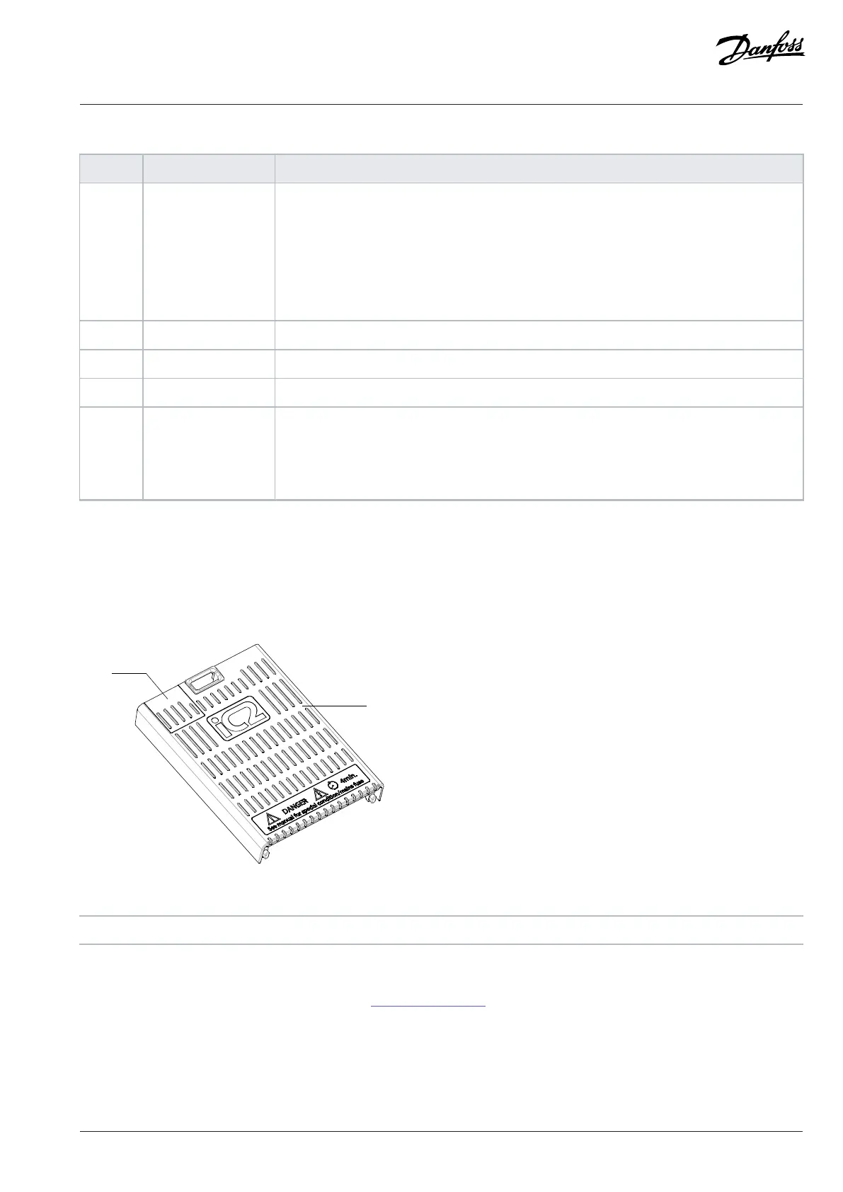
3.5.6 Sliding Door on the Terminal Cover
A sliding door, which is the protective cover of the RJ45 port, is designed on the terminal cover of the drive. When the drive is connected
with the Control Panel 2.0 OP2 option, which can be installed on the cabinet door, remove the sliding door to ensure that the terminal
cover remains on the drive to ensure safe operation.
Figure 10: Sliding Door on the Terminal Cover
1 Sliding door 2 Terminal cover
Disassembly
1. Remove the terminal cover with a screwdriver, see 3.5.1 Control Terminals.
2. From the inner side of the terminal cover, press the slot with a screwdriver to release the sliding door and slide it out.
Danfoss A/S © 2024.08 AJ402315027937en-000401 / 130R1239 | 25