Design Guide | iC2-Micro Frequency Converters Mechanical Installation Considerations
6.7.2 Mounting Locations
The drives are designed for installation in weather-protected environments. For more information, see 4.2.7.1 Overview of Ambient
Conditions.
The drive is mounted primarily on a wall or in an enclosed cabinet, the mounting surface must be solid, flat, and non-flammable.
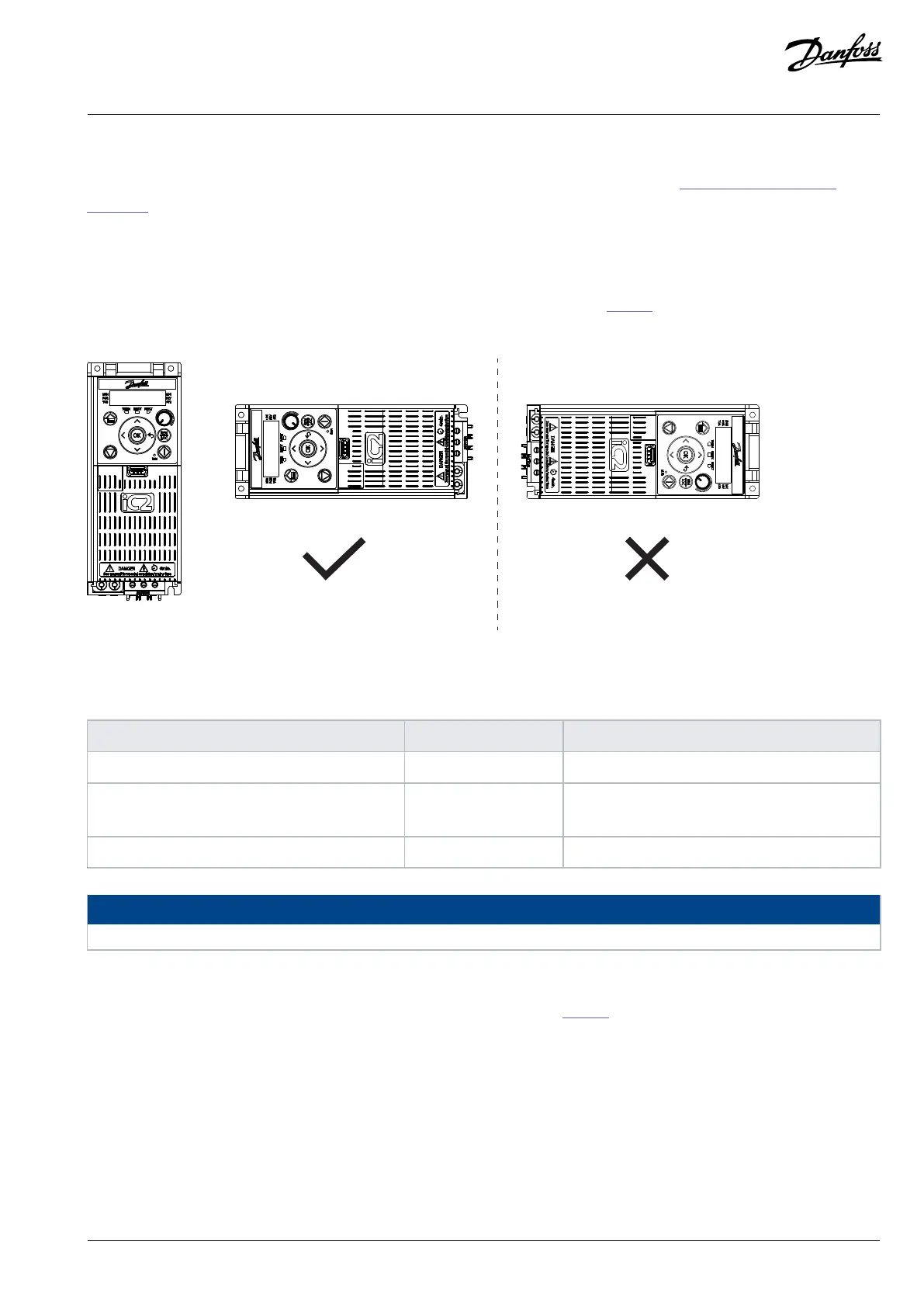
6.7.3 Mounting Directions
The drive can be mounted vertically or horizontally, depending on the enclosure size. See Table 48 for more information on the effects of
mounting direction on drive performance.
Figure 33: Mounting Directions for Drives
Table 48: Allowed Mounting Directions for IP20/Open Type Rated Drives and Effects of Mounting Direction on Performance
Installation direction Allowed enclosure size Effects on performance
A: Vertical installation All enclosure sizes None
B: Horizontal installation (Left side downwards) MA02c, MA01a–MA05a • Limited robustness to vibration and shock.
• Side-by-side mounting not possible.
C: Horizontal installation (Right side downwards) – Not allowed for all enclosure sizes.
NOTICE
The IP21/UL Type 1 rated drives are protected against dripping water when installed vertically.
6.7.4 Recommended Screws and Bolts
Check the recommended sizes of screws and bolts for mounting the drive in table Table 49.
Danfoss A/S © 2024.08 AJ402315027937en-000401 / 130R1239 | 69

 Loading...


