Ground the drive according to applicable standards and directives. Use a dedicated ground wire for input power, motor power, and
control wiring. Terminate individual ground wires separately, complying with the dimension requirements.
Follow motor manufacturers wiring requirements when connecting to the motors.
Keep the grounding wire as short as possible. The minimum cable cross-section for the ground wires is 10 mm
2
(7 AWG). Alternatively, it
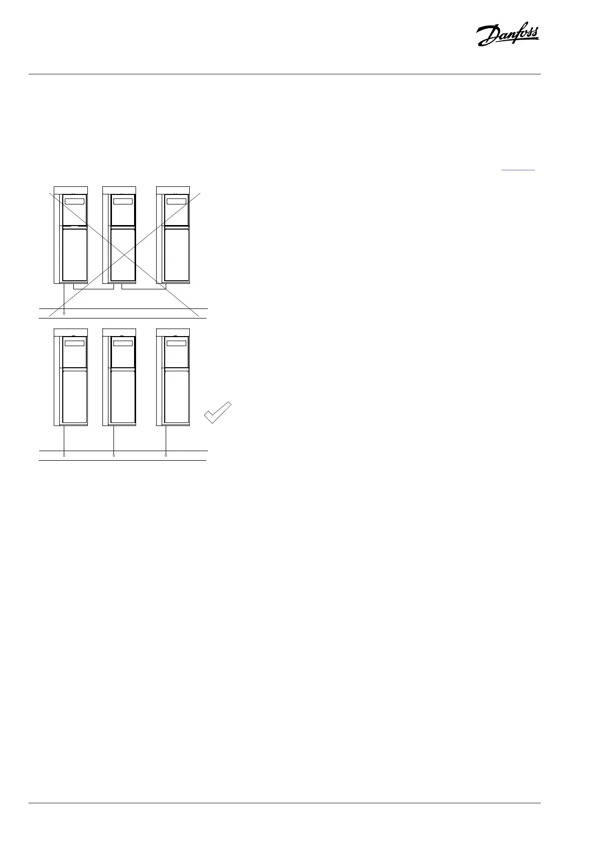
is possible to use 2 rated ground wires terminated separately. Do not ground drives to each other in a daisy-chain fashion (see Figure 41).
Figure 41: Grounding Principle
7.4.3 Control Cables
Use shielded cables for control wiring and avoid placing control wires next to power cables. Ideally, isolate the control cables from the
power cables (mains, motor, brake, and DC) by routing them separately or keep a minimum distance of 200mm (7.9in). For optional
shielding, both ends of the shielded control cables must have the shield connected.
Keep 24V signal cables apart from 110V or 230V signals from relays, for example.
When the drive is connected to a thermistor, ensure that the wiring is shielded and reinforced/double isolated. A 24VDC supply voltage
is recommended.
For communication purpose and command/control lines, follow the particular protocol standard.
7.5 Galvanic Isolation
PELV offers protection through extra low voltage. Protection against electric shock is ensured when the electrical supply is of the PELV
type and the installation is made as described in local/national regulations on PELV supplies.
All control terminals and relay terminals 01–03 comply with PELV (protective extra low voltage).
Galvanic (ensured) isolation is obtained by fulfilling requirements for higher isolation and by providing the relevant creapage/clearance
distances. These requirements are described in the EN 61800-5-1 standard.
82 | Danfoss A/S © 2024.08 AJ402315027937en-000401 / 130R1239
Design Guide | iC2-Micro Frequency Converters Electrical Installation Considerations