Design Guide | iC2-Micro Frequency Converters Electrical Installation Considerations
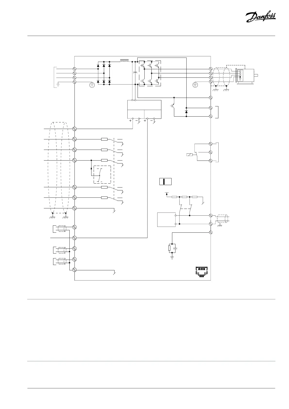
7.2 Wiring Diagram
e30bv083.12
RS485
interface
(N RS485) 69
(P RS485) 68
(COM RS485) 61
RS485
S640
0 V
S640
ON = Terminated
OFF = Open
1 2
ON
RS485 communication
RJ45 port
14 (D IN)
20 (COM I/O)
15 (D IN/OUT)
17 (D IN)
18 (D IN)
(NPN)
(PNP)
24 V
0 V
P9.4.1.1
32 (+10 V OUT)
33 (A IN)
34 (A IN)
35 (COM I/O)
31 (A OUT)
Figure 37: Wiring Diagram
1 Single DC choke in MA05a.
2 Built-in brake chopper is only applicable to drives in the power range of 3x380–480 V 2.2 kW (3.0 hp) and above, and 3x200–
240V 1.5kW (2hp) and above.
3 No BR terminals for 1x100–120 V, 1x200–240 V, 3x200–240 V 0.37–0.75 kW (0.5–1.0 hp), and 3x380-480 V 0.37-1.5kW
(0.5-2.0hp) drives.
4 Select the PNP or NPN mode via parameter P 9.4.1.1 Digital I/O mode (PNP=Source, NPN=Sink).
5 Use switch S640 (bus terminal) to enable termination on the RS485 port (terminals 68 and 69).
Danfoss A/S © 2024.08 AJ402315027937en-000401 / 130R1239 | 75