Figure 54: Twisted-pair Cables
1
Minimum 16 mm
2
(6 AWG)
2 Equalizing cable
Alternatively, the connection to terminal 61 can be omitted.
Figure 55: Twisted-pair Cables without Terminal 61
1
Minimum 16 mm
2
(6 AWG)
2 Equalizing cable
7.10.7 Load Sharing/Brake
Table 58: Connect Terminals
Load sharing -UDC and +UDC/+BR
Brake -BR and +UDC/+BR
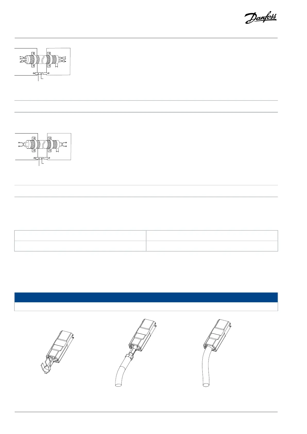
l For MA01a, MA02a, and MA03a drives, wire with recommended connector (Ultra- Pod Fully Insulated FASTON Receptacles and Tabs,
521366-2, TE connectivity).
l For other enclosure sizes, mount the wires to the related terminal and tighten. For required maximum screwing torque, see the back
of the terminal cover.
NOTICE
Voltage levels of up to 850 V DC may occur between terminals +UDC/+BR and -UDC. Not short-circuit protected.
Figure 56: Wiring the Connector for Load Sharing and Brake
96 | Danfoss A/S © 2024.08 AJ402315027937en-000401 / 130R1239
Design Guide | iC2-Micro Frequency Converters Electrical Installation Considerations