Design Guide | iC2-Micro Frequency Converters Electrical Installation Considerations
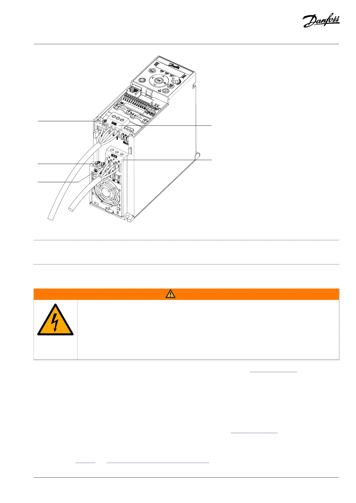
Figure 47: Mains, Motor, and Grounding Connection for 3-phase Units (Taking MA02a as an Example)
1 Grounding 2 Mains
3 Motor
7.10.2 Connecting the Motor
WARNING
INDUCED VOLTAGE
Induced voltage from output motor cables that run together can charge equipment capacitors, even with
the equipment turned off and locked out/tagged out. Failure to run output motor cables separately, or to use
shielded cables, could result in death or serious injury.
l Run output motor cables separately or use shielded cables.
l Simultaneously lock out/tag out all the drives.
l Comply with local and national electrical codes for cable sizes. For maximum cable sizes, see 4.4 Power Connectors.
l Follow motor manufacturer wiring requirements.
l Motor wiring knockouts or access panels are provided at the base of IP21/Type 1 units.
l Do not wire a starting or pole-changing device (for example, Dahlander motor or slip ring induction motor) between the drive and
the motor.
7.10.3 Connecting AC Mains
l Size the wiring based on the input current of the drive. For maximum wire sizes, see 4.4 Power Connectors.
l Comply with local and national electrical codes for cable sizes.
1. Connect the AC input power cables to terminals N and L for single-phase units, or to terminals L1, L2, and L3 for 3-phase units as
shown in Figure 48 (see 7.10.1 Mains, Motor, and Grounding Connectionfor more details).
Danfoss A/S © 2024.08 AJ402315027937en-000401 / 130R1239 | 91