Design Guide | iC2-Micro Frequency Converters Electrical Installation Considerations
7.3.3 PE Current Measurement
As the currents have different frequencies, it is not useful to measure an effective value only. Instead, it is required to perform a
frequency/FFT measurement. This can be done by using an appropriate oscilloscope or specific measuring equipment. Just analyzing the
effective value with a current clamp at the PE connection of the drive leads to insufficient and misleading results.
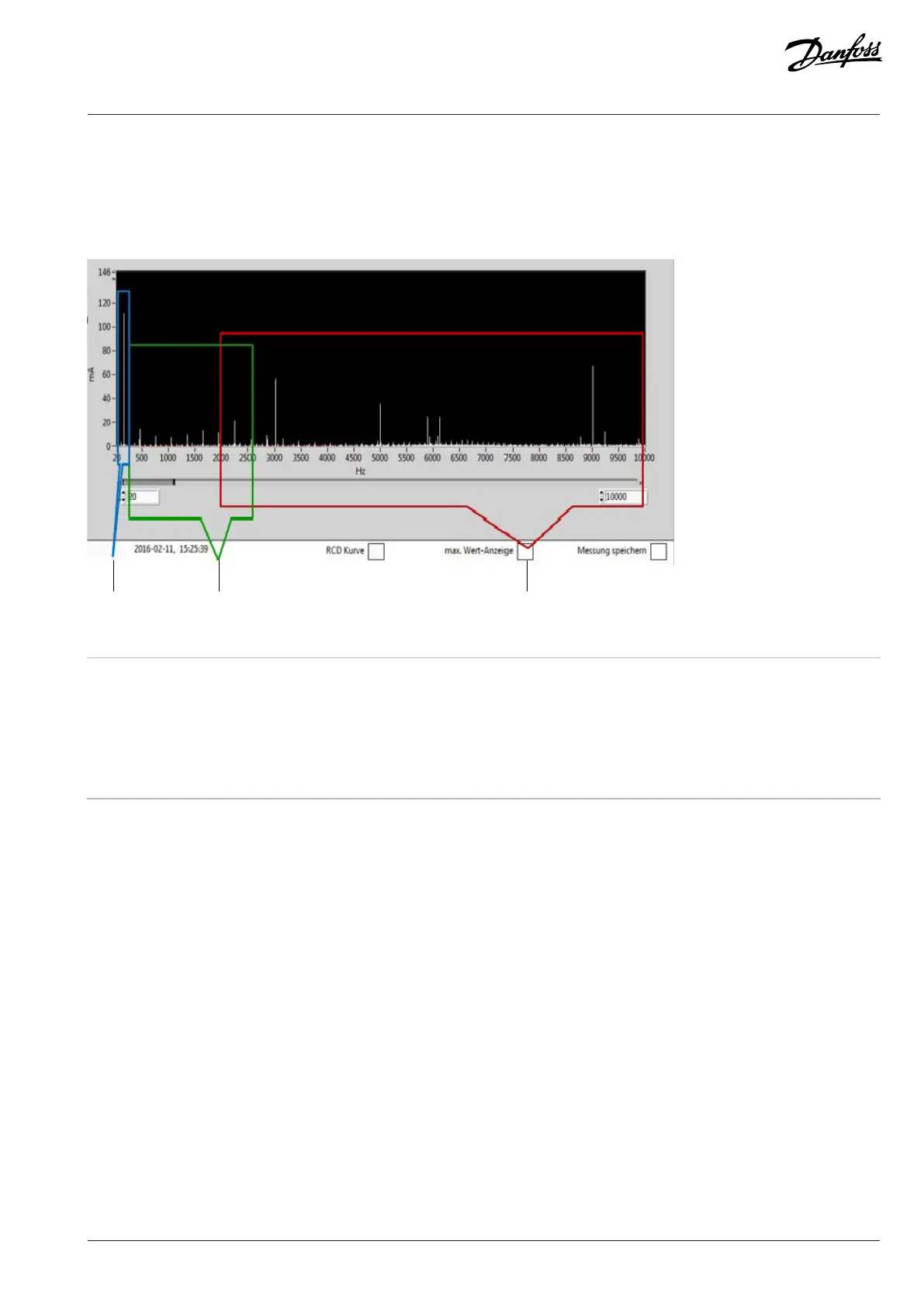
Figure 38: Example of FFT Measurement
1 f < 50Hz: Typical for inductive coupling in unsymmetrical
cables and conductor.
2 f = 150–2500Hz: Typical harmonic components in grid.
f = 150Hz: Common-mode current typical due to rectifier
with DC link.
3 f > 2kHz: Typical common-mode current due to capacitive
coupling between cable/motor and ground.
Danfoss A/S © 2024.08 AJ402315027937en-000401 / 130R1239 | 77